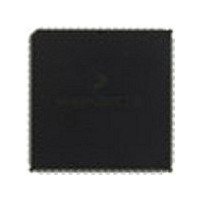
MC68HC000EI12 Freescale Semiconductor, MC68HC000EI12 Datasheet - Page 85

MC68HC000EI12
Manufacturer Part Number
MC68HC000EI12
Description
IC MPU 16BIT 10MHZ 68-PLCC
Manufacturer
Freescale Semiconductor
Specifications of MC68HC000EI12
Processor Type
M680x0 32-Bit
Speed
12MHz
Voltage
3.3V, 5V
Mounting Type
Surface Mount
Package / Case
68-PLCC
Family Name
M68000
Device Core
ColdFire
Device Core Size
16/32Bit
Frequency (max)
12MHz
Instruction Set Architecture
RISC
Supply Voltage 1 (typ)
5V
Operating Supply Voltage (max)
5.25V
Operating Supply Voltage (min)
4.75V
Operating Temp Range
0C to 70C
Operating Temperature Classification
Commercial
Mounting
Surface Mount
Pin Count
68
Package Type
PLCC
Lead Free Status / RoHS Status
Lead free / RoHS Compliant
Features
-
Lead Free Status / Rohs Status
Compliant
Available stocks
Company
Part Number
Manufacturer
Quantity
Price
Company:
Part Number:
MC68HC000EI12
Manufacturer:
FREESCALE
Quantity:
3 400
Company:
Part Number:
MC68HC000EI12
Manufacturer:
INTERSIL
Quantity:
1 980
Company:
Part Number:
MC68HC000EI12
Manufacturer:
Freescale Semiconductor
Quantity:
10 000
Company:
Part Number:
MC68HC000EI12R2
Manufacturer:
FREESCAL
Quantity:
8 831
Freescale Semiconductor, Inc.
Parameter #47 of Section 10 Electrical Characteristics is the asynchronous input setup
time. Signals that meet parameter #47 are guaranteed to be recognized at the next falling
edge of the system clock. However, signals that do not meet parameter #47 are not
guaranteed to be recognized. In addition, if DTACK is recognized on a falling edge, valid
data is latched into the processor (during a read cycle) on the next falling edge, provided
the data meets the setup time required (parameter #27). When parameter #27 has been
met, parameter #31 may be ignored. If DTACK is asserted with the required setup time
before the falling edge of S4, no wait states are incurred, and the bus cycle runs at its
maximum speed of four clock periods.
The late BERR in an MC68010 that is operating in a synchronous mode must meet setup
time parameter #27A. That is, when BERR is asserted after DTACK, BERR must be
asserted before the falling edge of the clock, one clock cycle after DTACK is recognized.
Violating this requirement may cause the MC68010 to operate erratically.
MOTOROLA
M68000 8-/16-/32-BIT MICROPROCESSORS USER'S MANUAL
5- 39
For More Information On This Product,
Go to: www.freescale.com


