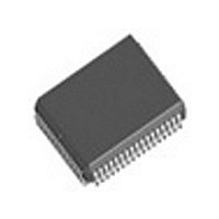
EG80C188EB25 Intel, EG80C188EB25 Datasheet - Page 59

EG80C188EB25
Manufacturer Part Number
EG80C188EB25
Description
IC MPU 16-BIT 5V 25MHZ 80-MQFP
Manufacturer
Intel
Specifications of EG80C188EB25
Processor Type
80C188
Features
EB suffix, 16-Bit, Extended Temp
Speed
25MHz
Voltage
5V
Mounting Type
Surface Mount
Package / Case
80-MQFP, 80-PQFP
Family Name
Intel186
Device Core Size
16b
Frequency (max)
25MHz
Instruction Set Architecture
CISC
Supply Voltage 1 (typ)
5V
Operating Supply Voltage (max)
5.5V
Operating Supply Voltage (min)
4.5V
Operating Temp Range
0C to 70C
Operating Temperature Classification
Commercial
Mounting
Surface Mount
Pin Count
68
Package Type
PLCC
Lead Free Status / RoHS Status
Lead free / RoHS Compliant
Other names
864094
Available stocks
Company
Part Number
Manufacturer
Quantity
Price
Part Number:
EG80C188EB25
Manufacturer:
INTEL
Quantity:
20 000
ERRATA
An 80C186EB 80L186EB with a STEPID value of
0001H has the following known errata A device with
a STEPID of 0001H can be visually identified by the
presence of an ‘‘A’’ alpha character next to the
FPO number The FPO number location is shown in
Figures 4 5 and 6
1 A19 ONCE is not latched by the rising edge of
2 During interrupt acknowledge (INTA) bus cycles
3 CLKOUT will transition off the rising edge of
4 RESIN has a hysterisis of only 130 mV It is rec-
RESIN A19 ONCE must remain active (LOW) at
all times to remain in the ONCE Mode Removing
A19 ONCE after RESIN is high will return all out-
put pins to a driving state
80C186EB will remain in a reset state
the bus controller will ignore the state of the
READY pin if the previous bus cycle ignored the
state of the READY pin This errata can only oc-
cur if the Chip-Select Unit is being used All active
chip-selects must be programmed to use READY
(RDY bit must be programmed to a 1) if wait-
states are required for INTA bus cycles
CLKIN rather than the falling edge of CLKIN This
does not affect any bus timings other than T
ommended that RESIN be driven by a Schmitt
triggered device to avoid processor lockup during
reset using an RC circuit
however
CD
the
80C186EB 80C188EB 80L186EB 80L188EB
5 SINT1 will only go active for one clock period
An 80C186EB 80L186EB with a STEPID value of
0001H or 0002H has the following known errata A
device with a STEPID of 0002H can be visually iden-
tified by noting the presence of a ‘‘B’’ ‘‘C’’ ‘‘D’’ or
‘‘E’’ alpha character next to the FPO number The
FPO number location is shown in Figures 4 5 and 6
1 An internal condition with the interrupt controller
REVISION HISTORY
This data sheet replaces the following data sheets
270803-004 80C186EB
270885-003 80C188EB
270921-003 80L186EB
270920-003 80L188EB
272311-001 SB80C188EB SB80L188EB
272312-001 SB80C186EB SB80L186EB
when a receive or transmit interrupt is pending
(i e it does not remain active until the S1STS
register is read) If SINT1 is to be connected to
any of the processor interrupt lines (INT0 – INT4)
then it must be latched by user logic
can cause no acknowledge cycle on the INTA1
line in response to INT1 This errata only occurs
when Interrupt 1 is configured in cascade mode
and a higher priority interrupt exists This errata
will not occur consistantly it is dependent on in-
terrupt timing
59


