AVM3225P9 Panasonic, AVM3225P9 Datasheet - Page 5
AVM3225P9
Manufacturer Part Number
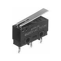
AVM3225P9
Description
Basic / Snap Action / Limit Switches 100mA to 5A, Hinge Lever, Solder
Manufacturer
Panasonic
Datasheet
1.AVM3225P9.pdf
(5 pages)
Specifications of AVM3225P9
Contact Rating
100 mAmps to 5 Amps
Actuator
Lever
Operating Force
1.47 N
Termination Style
Solder
Lead Free Status / Rohs Status
Lead free / RoHS Compliant


NOTES
1. Fastening of the switch body
1) Use flat filister head M2.3 screws to
mount switches with less than a 0.29 N·m
torque. Use of screws washers or
adhesive lock is recommended to prevent
loosening of the screws.
2) Check insulation distance between
ground and each terminal.
3) When the operation object is in the
free position, force should not be applied
directly to the actuator or pin plunger
from vertical direction to the switch.
4) In setting the movement after
operation, the over-travel should be set
more than 70% as a standard. Setting the
movement at less than 70% of O.T. may
cause troubles such as miscontact and
welding due to small contact force of the
switch.
5) For a lever type, the force from the
reverse and side to the operation
direction should not be applied.
All Rights Reserved © COPYRIGHT Panasonic Electric Works Co., Ltd.
2. Soldering operations
Manual soldering should be
accomplished within 3 seconds with max.
350°C iron.
Care should be taken not to apply force
to the terminals during soldering.
Terminal portions must not be moved in
min.1 minute after soldering.
Also no tensile strength of lead wires
should be applied to terminals.
3. Selection of the switch
When specifying the switch, allow ±20%
to the listed operating characteristics.
4. Environment
Avoid using the switches in the following
conditions;
• In corrosive gases, such as silicon gas
• In a dusty environment
5. Cautions regarding use
When switching low-level circuits (6V DC
5mA, 12V DC 2mA, 24V DC 1mA), AV,
AV3/AVT3, AVL3 Au clad contact type
switches are recommended. When used
to switch inductive loads (relays,
solenoids, buzzers, etc.), it is
recommended that a proper spark
quench circuit is inserted in the switch to
prevent contact faults caused by electric
arcs. Care should be taken that
occurrence in AC load possibly shorten
the expected life.
6. Quality check under actual loading
conditions
To assure reliability, check the switch
under actual loading conditions. Avoid
any situation that may adversely affect
switching performance.
AVM3
P
Related parts for AVM3225P9
Image
Part Number
Description
Manufacturer
Datasheet
Request
R

Part Number:
Description:
Coin Cell Battery with Leads 3V 20mAH 2 PIN HORZ
Manufacturer:
Panasonic
Datasheet:
Part Number:
Description:
Coin Cell Battery with Leads 3V 48mAh 2 pin Vert
Manufacturer:
Panasonic
Part Number:
Description:
Coin Cell Battery 3V 12 X 2.5 mm 48mA
Manufacturer:
Panasonic
Datasheet:
Part Number:
Description:
Coin Cell Battery 3V 48mAh W/TABS
Manufacturer:
Panasonic
Datasheet:
Part Number:
Description:
Color CCD Linear Image Sensor with 1024 Pixels for R and B Colors/2048 Pixels for G Color
Manufacturer:
Panasonic
Datasheet:
Part Number:
Description:
2048-Bit CCD Linear Image Sensor
Manufacturer:
Panasonic
Datasheet:
Part Number:
Description:
2592-Bit CCD Linear Image Sensor
Manufacturer:
Panasonic
Datasheet:
Part Number:
Description:
2048-Bit High-Responsivity CCD Linear Image Sensor with Internal Clock Driver
Manufacturer:
Panasonic
Datasheet:
Part Number:
Description:
2880-Bit High-Responsivity CCD Linear Image Sensor
Manufacturer:
Panasonic
Datasheet:
Part Number:
Description:
Color CCD Linear Image Sensor with 512 Pixels for R and B Colors/1024 Pixels for G Color
Manufacturer:
Panasonic
Datasheet:
Part Number:
Description:
Quad analog switches
Manufacturer:
Panasonic
Datasheet:
Part Number:
Description:
ICs for TV
Manufacturer:
Panasonic
Datasheet:
Part Number:
Description:
IC for Liquid Crystal Color TV
Manufacturer:
Panasonic
Datasheet:
Part Number:
Description:
VCR cylinder direct motor drive circuit
Manufacturer:
Panasonic
Datasheet: