RY-5W-K Fujitsu, RY-5W-K Datasheet - Page 4
RY-5W-K
Manufacturer Part Number
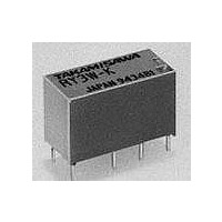
RY-5W-K
Description
Low Signal Relays - PCB SIGNAL
Manufacturer
Fujitsu
Specifications of RY-5W-K
Contact Form
2 Form C (DPDT)
Coil Voltage
5 VDC
Coil Type
High Sensitivity
Power Consumption
150 mW
Termination Style
DIL Pitch
Maximum Switching Current
1 A
Lead Free Status / Rohs Status
Lead free / RoHS Compliant
Available stocks
Company
Part Number
Manufacturer
Quantity
Price
Company:

Part Number:
RY-5W-K
Manufacturer:
PANASONIC
Quantity:
12 000
Part Number:
RY-5W-K
Manufacturer:
TAKAMISAWA高见泽
Quantity:
20 000
Company:
Part Number:
RY-5W-K-UL
Manufacturer:
SAMSUNG
Quantity:
4 123


n INSULATION
*
*
n SPECIFICATIONS
Time Value
1
2
Item
Isolation (initial)
Dielectric
Strength
Surge Voltage
Minimum switching loads mentioned above are reference values. Please perform the confirmation test with the actual load
Contact
Coil
Life
Other
before production since reference values may vary according to switching frequencies, environmental conditions and ex-
pected reliability levels.
48VDC type
Arrangement
Material
Style
Resistance (initial)
Maximum Carrying Current
Rating (resistive)
Maximum Switching Power
Maximum Switching Voltage
Maximum Switching Current
Minimum Switching Load*
Capacitance (at 10MHz)
Nominal Power (at 20°C)
Operate Power (at 20°C)
Operating Temperature (No frost)
Operate (at nominal voltage)
Release (at nominal voltage)
Mechanical
Electrical (at contact rating)
Vibration
Resistance Endurance
Shock Misoperation
Resistance Endurance
Weight
Item
open contact
coil and contact/
adjacent contacts
Misoperation
1
Sensitive
Minimum 1,000 MΩ (at 500VDC)
500VAC 1 min.,
1,000VAC 1 min.,
1500V (coil-contact) (10/160 µs standard wave)
2 form C (DPDT)
Gold overlay silver-palladium
Bifurcated (cross bar)
Maximum 100 mΩ (at 1 A 6 VDC)
1.25 A 2 A
1 A 24 VD
0.5 A 120 VAC
60 VA/24 W
120 VAC, 60 VDC
1 A
0.01 mA 10 mVDC
A pprox. 0.9 pF (between open contacts) 1.4 pF (adjacent contacts)
Approx. 1.9 pF (between coil and contacts)
150 to 300 mW 500 to 580 mW 450 to 460 mW
75 to 140 mW
–30°C to +90°C –30°C to +60°C (
(*+80ºC)
Maximum 6 ms
Maximum 3 ms
2 × 10
2 × 10
5 × 10
10 to 55 Hz (double amplitude of 1.5 mm)
10 to 55 Hz (double amplitude of 4.5 mm)
100 m/s
1,000 m/s
Approximately 5 g
RY-( ) W-K
Sensitive
High
Type
5
5
7
ops. min. (0.5 A 120 VAC)
ops. min. ( 1 A 24 VD C)
ops. min. 1 × 10
2 A
2
2
(11±1 ms)
( 6±1 ms)
500mW
125 to 145 mW 200 to 210 mW
RY-( ) WZ-K RY-( ) WF-K
30 VA/24 W
500 mW
Type
7
operations minimum
0.25 A 120 VAC
(0.25 A 120 VAC
1 A 24 VDC
5 × 10
High Isolation
1,000VAC 1 min.,
refer to the CHARACTERISTIC DATA
1 A 24 VDC
Dielectric
Strength
High
5
(*
ops. min.
125 VAC, 150 VDC 120 VAC, 60 VDC
500 to 580 mW
200 to 324 mW
silver-nickel
(2 A 30 VDC)
RY-( ) WFZ-K
62.5 VA/60 W 36 VA/7.2 W
1 × 10
0.5 A 125 VAC
Gold overlay
2 A 30 VDC
RY SERIES
2 A Type
5
ops. min.
2A
500VAC 1 min.,
0.6 A
0.6 A
) –30°C to +70°C
450 to 480 mW
200 to 210 mW
silver-palladium
1 × 10
2 Form D (2 MBB)
0.1 mA 10 mVDC
2 × 10
(0.3 A 120 VAC)
0.15 A 48 VDC
0.3 A 120 VAC
Single
5 × 10
(0.15 A 48 VDC)
Continuous
2
RY-( ) D-K
MBB
+65ºC)
Gold overlay
(MBB)
Type
6
5
5
ops. min.
opsmin.
ops. min.
4
Related parts for RY-5W-K
Image
Part Number
Description
Manufacturer
Datasheet
Request
R

Part Number:
Description:
Low Signal Relays - PCB Mini Signal 12VDC
Manufacturer:
Fujitsu

Part Number:
Description:
Fujitsu Media Devices Limited [NMOS 1- CHANNEL, 13-BIT AND 3-CHANNEL, 6-BIT D/A CONVERTER]
Manufacturer:
Fujitsu
Datasheet:
Part Number:
Description:
Fujitsu Media Devices Limited [32-bit RISC Microcontroller]
Manufacturer:
Fujitsu
Datasheet:
Part Number:
Description:
Fujitsu Media Devices Limited [MOS 262,144 BIT DYNAMIC RANDOM ACCESS MEMORY]
Manufacturer:
Fujitsu
Datasheet:
Part Number:
Description:
Fujitsu Media Devices Limited [PROGRAMMABLE TIMER]
Manufacturer:
Fujitsu
Datasheet:
Part Number:
Description:
Fujitsu Media Devices Limited [MOS Universal Asynchronous receiver/transmitter(UART)]
Manufacturer:
Fujitsu
Datasheet: