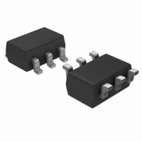
PIC10F200T-E/OT Microchip Technology, PIC10F200T-E/OT Datasheet - Page 3

PIC10F200T-E/OT
Manufacturer Part Number
PIC10F200T-E/OT
Description
IC PIC MCU FLASH 256X12 SOT23-6
Manufacturer
Microchip Technology
Series
PIC® 10Fr
Datasheets
1.PIC10F200T-IOT.pdf
(96 pages)
2.PIC10F200T-IOT.pdf
(6 pages)
3.PIC10F200T-IOT.pdf
(18 pages)
4.AC162052.pdf
(54 pages)
Specifications of PIC10F200T-E/OT
Core Size
8-Bit
Program Memory Size
384B (256 x 12)
Core Processor
PIC
Speed
4MHz
Peripherals
POR, WDT
Number Of I /o
3
Program Memory Type
FLASH
Ram Size
16 x 8
Voltage - Supply (vcc/vdd)
2 V ~ 5.5 V
Oscillator Type
Internal
Operating Temperature
-40°C ~ 125°C
Package / Case
SOT-23-6
Controller Family/series
PIC10
No. Of I/o's
4
Ram Memory Size
16Byte
Cpu Speed
4MHz
No. Of Timers
1
Digital Ic Case Style
SOT-23
Processor Series
PIC10F
Core
PIC
Data Bus Width
8 bit
Data Ram Size
16 B
Interface Type
USB
Maximum Clock Frequency
4 MHz
Number Of Programmable I/os
4
Number Of Timers
1
Operating Supply Voltage
2 V to 5.5 V
Maximum Operating Temperature
+ 125 C
Mounting Style
SMD/SMT
3rd Party Development Tools
52715-96, 52716-328, 52717-734
Development Tools By Supplier
PG164130, DV164035, DV244005, DV164005, PG164120
Minimum Operating Temperature
- 40 C
Package
6SOT-23
Device Core
PIC
Family Name
PIC10
Maximum Speed
4 MHz
Lead Free Status / RoHS Status
Lead free / RoHS Compliant
For Use With
AC162059 - HEADER INTRFC MPLAB ICD2 8/14PINXLT06SOT - SOCKET TRAN ICE 6SOT W/CABLEAC164321 - MODULE SKT 6L PM3 SOT23AC164037 - MODULE SKT 6L PROMATE II SOT23
Eeprom Size
-
Data Converters
-
Connectivity
-
Lead Free Status / Rohs Status
Details
Other names
PIC10F200T-E/OT
PIC10F200T-E/OTTR
PIC10F200T-E/OTTR
Available stocks
Company
Part Number
Manufacturer
Quantity
Price
PROGRAMMING DETAILS
GENERAL HEADER SETUP
© 2009 Microchip Technology Inc.
The header board is designed to be used with the in-circuit emulator or the in-circuit
debugger selected as a debugger, not a programmer, in MPLAB IDE. Any program-
ming of the ICE/ICD device on the header is for debug purposes and includes the
debug executive. See your related debug tool documentation for details on using it as
a debugger.
To program production (non-ICE/ICD) devices with your debug tool, use the Universal
Programming Module (AC162049) or design a modular interface connector on the
target. See the appropriate specification for connections. For the most up-to-date
device programming specifications, see the Microchip website (www.microchip.com).
Also, production devices may be programmed with the following tools:
• MPLAB PM3 device programmer
• PICSTART
• PICkit™ 1, 2 or 3 development programmer
• MPLAB ICD 3
• MPLAB REAL ICE in-circuit emulator
To set up your header, do the following:
1. Check the header board for any stickers and the header box for any paper inserts
FIGURE 3:
2. Set any jumpers or switches on the header to determine device functionality or
that may specify special operating instructions (Figure 3). Follow these
instructions before doing anything else.
selection as specified for that header. See the sections “Optional Headers” or
“Required Headers” for information on how to set up individual headers.
®
Plus development programmer
SPECIAL HEADER INSTRUCTIONS
Header Board Specification
Header Board (Top)
CAUTION
DS51292R-page 3


