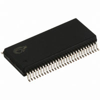
CY7C66113-PVC Cypress Semiconductor Corp, CY7C66113-PVC Datasheet - Page 28

CY7C66113-PVC
Manufacturer Part Number
CY7C66113-PVC
Description
IC MCU 8K USB HUB 4 PORT 56TSSOP
Manufacturer
Cypress Semiconductor Corp
Specifications of CY7C66113-PVC
Applications
USB Hub/Microcontroller
Core Processor
M8
Program Memory Type
OTP (8 kB)
Controller Series
USB Hub
Ram Size
256 x 8
Interface
I²C, USB, HAPI
Number Of I /o
31
Voltage - Supply
4 V ~ 5.5 V
Operating Temperature
0°C ~ 70°C
Mounting Type
Surface Mount
Package / Case
56-SSOP
Operating Temperature (max)
70C
Operating Temperature (min)
0C
Operating Temperature Classification
Commercial
Mounting
Surface Mount
Pin Count
56
Lead Free Status / RoHS Status
Contains lead / RoHS non-compliant
For Use With
CY3649 - PROGRAMMER HI-LO USB M8428-1339 - KIT LOW SPEED PERSONALITY BOARD
Lead Free Status / RoHS Status
Not Compliant, Contains lead / RoHS non-compliant
Other names
428-1330
Available stocks
Company
Part Number
Manufacturer
Quantity
Price
Company:
Part Number:
CY7C66113-PVC
Manufacturer:
CY
Quantity:
10
indicate this port is low speed. Then the hub repeater generates a “Hub Interrupt”, if the interrupt is enabled, to notify the
microcontroller that there has been a change in the Hub downstream status.
A high-speed (12 Mbps) USB device will have a pull-up resistor from the D+ pin. That means the hub will see a HIGH on D+ and
a LOW on D–. This tells the hub that a full-speed device is connected to the port. The hub repeater sets a connect bit in the Hub
Port Connect Status register, clears a bit in the Hub Port Speed register (high-speed), and generates a Hub Interrupt, if enabled,
to ask the microcontroller to read the Hub status.
When a USB device is disconnected from the Hub, the differential signal pair will eventually reach a single-ended-zero state when
the hub is not driving data to the port. The hub repeater will recognize the SE0 as a disconnect and clear the corresponding bit
in the Hub Port Connect Status register. Then generates a Hub interrupt, if enabled, to the microcontroller.
The Hub Port Connect Status register is cleared to zero by reset, then set to match the hardware configuration by the hub repeater
hardware. The Reserved bits [7:4] should always read as ‘0’ to indicate no connection.
The Hub Port Speed register is cleared to zero by reset, then set to match the hardware configuration by the hub repeater
hardware. A zero setting indicates a high speed device. The Reserved bits [7:4] should always read as ‘0.’
17.2
After a USB device connection has been detected and reported to the microcontroller, the firmware needs to update status bits
in the hub status data structure that is polled periodically by the USB host. The host responds by sending a packet that instructs
the hub to enable the downstream port. The microcontroller responds to the packet by setting a bit in the Hub Port Enable register
for the downstream port. The hub repeater hardware responds to an enable bit in the Hub Port Enable register by enabling the
downstream port. Then the USB host enumerates the device that was just detected.
When a USB device disconnection has been detected and reported to the microcontroller, the firmware needs to update status
bits in the hub status data structure that is polled periodically by the USB host. The host responds by sending a packet that
instructs the hub to disable the downstream port. The microcontroller responds to the packet by clearing a bit in the Hub Port
Enable register for the downstream port. The hub repeater hardware responds to the deassertion of the enable bit by disabling
the downstream port.
The Hub Port Enable register is cleared to zero by reset to disable all downstream ports as the default condition. A bit will also
be cleared by the hub interface if babble is detected on that downstream port.
17.3
Data transfer on hub downstream ports is controlled according to the bit settings of the Hub Downstream Ports Control Register
(0x4B). Each downstream port is controlled by two bits. the control bits are defined in the table below. The Hub Downstream Ports
Control Register is cleared upon reset.
Reserved
Reserved
Reserved
Port 4(1)
7
7
7
7
Enabling/Disabling a USB Device
Hub Downstream Ports Status and Control
Reserved
Reserved
Reserved
Port 4(0)
6
6
6
6
Figure 17-4. Hub Downstream Ports Control Register 0x4B (read/write)
Figure 17-3. Hub Port Enable Register 0x49 (read/write)
Figure 17-1. Hub Port Connect Status 0x48 (read only)
Reserved
Reserved
Reserved
Port 3(1)
5
5
5
5
Figure 17-2. Hub Port Speed 0x4A (read only)
PRELIMINARY
Reserved
Reserved
Reserved
Port 3(0)
4
4
4
4
28
Port 2(1)
Port 4
Port 4
Port 4
3
3
3
3
Port 2(0)
Port 3
Port 3
Port 3
2
2
2
2
CY7C66011/12/13
CY7C66111/12/13
Port 1(1)
Port 2
Port 2
Port 2
1
1
1
1
Port 1(0)
Port 1
Port 1
Port 1
0
0
0
0


