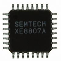
XE8807AMI026TLF Semtech, XE8807AMI026TLF Datasheet - Page 104

XE8807AMI026TLF
Manufacturer Part Number
XE8807AMI026TLF
Description
IC MCU LOW PWR MTP FLASH 32-TQFP
Manufacturer
Semtech
Datasheet
1.XE8807AMI026TLF.pdf
(143 pages)
Specifications of XE8807AMI026TLF
Applications
Sensing Machine
Core Processor
RISC
Program Memory Type
FLASH (11 kB)
Controller Series
XE8000
Ram Size
512 x 8
Interface
UART, USRT
Number Of I /o
24
Voltage - Supply
2.4 V ~ 5.5 V
Operating Temperature
-40°C ~ 85°C
Mounting Type
Surface Mount
Package / Case
32-TQFP, 32-VQFP
For Use With
XE8000MP - PROG BOARD AND PROSTART2 CARD
Lead Free Status / RoHS Status
Lead free / RoHS Compliant
Other names
XE8807AMI026TR
Available stocks
Company
Part Number
Manufacturer
Quantity
Price
Company:
Part Number:
XE8807AMI026TLF
Manufacturer:
IDT
Quantity:
62
14.12.2.4.2
We then set-up the RF interface of the microcontroller circuit as a receiver (RfifEnRx = 1 and RfifEnTx = 0).
Assume that the RC clock frequency used in the microcontroller is 1.0 MHz. To select the correct baud rate of 4.8
kbit/s according to the equation in chapter 14.10 (attention: the baud rate is twice the bit rate in the Manchester
code), fine*coarse=1.0e06/(16*4.8e3)=13.0. This can be done by setting RfifBRCoarse = 00 and RfifBRFine =
1100.
The external bit synchronization clock is switched off by clearing the bit RfifRxClock = 0.
The decoder is enabled and set to Manchester Level decoding by setting RfifEnCod = 1 and RfifPCM = 011.
The start detection by protocol violation is enabled by setting RfifEnStart = 01.
The start sequence detection interrupt is enabled by setting RfifRxIrqEn = 001.
The set-up of the interface is summarized in the Table 14-30.
14.12.2.4.3
In order to handle the received data by interrupt, enable the RF interface reception interrupt in the interrupt handler
of the circuit.
Data received before the first start pattern detection after the enabling of the interface are not relevant since we are
not yet synchronized to the messages. Sine the start detection interrupt has been enabled, nothing has to be done
until the interrupt occurs.
When the first interrupt occurs, we are synchronized to the messages. In order to read data in an efficient way, the
interrupt source is modified and set to “Rx FIFO full” by writing 100 to RfifRxIrqEn. Once this is done, we can wait
for the next interrupt to download the received message.
At each new interrupt, we can now read 4 bytes of the received message by reading the register RegRfifRx 4
consecutive times. The interrupt should be served before the next byte is received since otherwise data may be
lost by lack of space in the FIFO (overrun error which sets the flag RfifRxFifoOverrun) or because the start
sequence of the next message is detected which resets the reception FIFO.
When the complete message is received, the start sequence detection interrupt may be enabled again
(RfifRxIrqEn = 001) and the sequence starts all over again.
© Semtech 2006
Pattern1
Pattern2
Pattern3
Pattern4
Table 14-29. XE1202A register set-up (see XE1202A datasheet for bit explanation)
RF interface set-up
Data reception
RegRfifCmd1
RegRfifCmd2
RegRfifCmd3
01000
01001
01010
01011
Register
Table 14-30. RF interface set-up
14-24
0
0
0
0
0
0
0
0
0
0
0
0
00000010
10100100
00100010
contents
0
0
0
0
0
0
0
0
0
0
0
0
XE8806A/XE8807A
0
0
0
0
0
0
0
0
www.semtech.com


