20-101-1256 Rabbit Semiconductor, 20-101-1256 Datasheet - Page 45
20-101-1256
Manufacturer Part Number
20-101-1256
Description
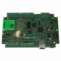
COMPUTER SINGLE-BOARD BL4S110
Manufacturer
Rabbit Semiconductor
Datasheet
1.20-101-1258.pdf
(144 pages)
Specifications of 20-101-1256
Module/board Type
Single Board Computer Module
Product
Modules
Processor Type
Rabbit 4000
Sram
512 KB
Flash
1 MB
Timers
8 bit, 10 bit
Number Of I/os
20
Backup Battery
3 V Lithium Coin Type
Operating Voltage
9 V to 36 V
Board Size
96 mm x 146 mm x 16 mm
Description/function
Computer Module
For Use With/related Products
BL4S110
Lead Free Status / RoHS Status
Lead free / RoHS Compliant
Other names
316-1169


4.2.2 Serial Communication
The following sample programs are found in the
•
•
•
•
BL4S100 User’s Manual
PARITY.C
to Serial Port F. The program will cycle through parity types on Serial Port D. Serial
Port F will always be checking parity, so parity errors should occur during most
sequences. The results are displayed in the Dynamic C
Connect Tx/1-W to CTS (RxF) on header J5 before compiling and
running this sample program. You may wish to do
the program to see the data, which go by rather quickly.
SIMPLE3WIRE.C
serial communication using the Dynamic C
low these instructions before running this sample program.
Connect Tx/1-W to CTS (RxF), then connect Rx to RTS (TxF)
before compiling and running this sample program.
SIMPLE5WIRE.C
using the Dynamic C
sample program.
Before you compile and run this sample program, connect Tx/1-W
to Rx, then connect RTS to CTS.
To test flow control, disconnect RTS from CTS while running this
program. Characters should stop printing in the Dynamic C
window and should resume when RTS and CTS are connected again.
COMPUTER_PARITY.C
three-wire RS-232 connection. Parity is selected for the BL4S100 and for the serial ter-
minal emulation program. Characters typed in either the Dynamic C
in the serial terminal emulation program are echoed in both displays. Parity errors are
counted and displayed by the Rabbit microprocessor on the BL4S100.
Before you compile and run this sample program, use the
long serial cable (Part No. 540-0094) to connect Tx (brown
wire), Rx (red wire) and GND (black wire) on header J5 to
a PC COM port.
Open a Hyperterminal session (
Communications
connected to and set the default serial parameters:
NOTE: For the sequence that does yield parity errors, the errors won't
Bits per second:
Data bits: 8
Parity: None
occur for each byte received. This is because certain byte patterns along with the stop bit will
appear to generate the correct parity for the UART.
—This sample program repeatedly sends byte values 0–127 from Serial Port D
115200
—This program demonstrates basic RS-232
—This program demonstrates 5-wire RS-232 serial communication
). Select the PC COM port the cable is
STDIO
—This sample program demonstrates using parity over a simple
window. Follow these instructions before running this
Start > Accessories >
STDIO
SAMPLES\BL4S1xx\RS232
<Ctrl-Q>
window. Fol-
STDIO
STDIO
to stop
window.
STDIO
subdirectory.
window or
43
Related parts for 20-101-1256
Image
Part Number
Description
Manufacturer
Datasheet
Request
R

Part Number:
Description:
COMPUTER SGL-BRD BL2500 29.4MHZ
Manufacturer:
Rabbit Semiconductor
Datasheet:

Part Number:
Description:
COMPUTER SGL-BRD BL2500 29.4MHZ
Manufacturer:
Rabbit Semiconductor
Datasheet:

Part Number:
Description:
DISPLAY GRAPHIC 12KEY PROG OP670
Manufacturer:
Rabbit Semiconductor
Datasheet:
Part Number:
Description:
DISPLAY GRAPHIC 12KEY ETH OP6700
Manufacturer:
Rabbit Semiconductor
Datasheet:

Part Number:
Description:
COMPUTER SINGLE-BOARD BL2030
Manufacturer:
Rabbit Semiconductor
Part Number:
Description:
COMPUTER SGL-BOARD ETH BL2010
Manufacturer:
Rabbit Semiconductor

Part Number:
Description:
MODULE OP6810 W/O ETH/MEM EXPANS
Manufacturer:
Rabbit Semiconductor
Datasheet:
Part Number:
Description:
COMPUTER SINGLE-BOARD BL2020
Manufacturer:
Rabbit Semiconductor
Part Number:
Description:
COMPUTER BL2010 W/FRICTION LOCK
Manufacturer:
Rabbit Semiconductor
Part Number:
Description:
COMPUTER BL2020 W/FRICTION LOCK
Manufacturer:
Rabbit Semiconductor
Part Number:
Description:
COMPUTER SGL-BRD BL2500 44.2MHZ
Manufacturer:
Rabbit Semiconductor
Datasheet:
Part Number:
Description:
COMPUTER SGL-BOARD FULL BL2000
Manufacturer:
Rabbit Semiconductor

Part Number:
Description:
COMPUTER SINGLE-BOARD BL2110
Manufacturer:
Rabbit Semiconductor

Part Number:
Description:
COMPUTER SGL-BRD 29.4MHZ BL2610
Manufacturer:
Rabbit Semiconductor
Datasheet:
Part Number:
Description:
INTERFACE OP6800 512K FLASH&SRAM
Manufacturer:
Rabbit Semiconductor
Datasheet: