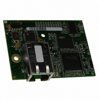
20-101-1131 Rabbit Semiconductor, 20-101-1131 Datasheet - Page 23

20-101-1131
Manufacturer Part Number
20-101-1131
Description
MODULE RCM4200 RABBITCORE
Manufacturer
Rabbit Semiconductor
Datasheet
1.20-101-1132.pdf
(134 pages)
Specifications of 20-101-1131
Module/board Type
MPU Core Module
Product
Microcontroller Modules
Core Processor
Rabbit 4000
Flash
512 KBytes
Operating Supply Voltage
3 to 3.6 V
Board Size
61 mm x 47 mm x 21 mm
Cpu Core
Rabbit 4000
For Use With/related Products
RCM4200
Lead Free Status / RoHS Status
Lead free / RoHS Compliant
Other names
316-1124
- Current page: 23 of 134
- Download datasheet (2Mb)
•
•
Once you have loaded and executed these five programs and have an understanding of
how Dynamic C and the RCM4200 modules interact, you can move on and try the other
sample programs, or begin building your own.
User’s Manual
TAMPERDETECTION.C
mode. When an attempt is detected, the battery-backed onchip-encryption RAM on the
Rabbit 4000 is erased. This battery-backed onchip-encryption RAM can be useful to
store data such as an AES encryption key from a remote location.
This sample program shows how to load and read the battery-backed onchip-encryption
RAM and how to enable a visual indicator.
Once this sample is compiled and running (you pressed the
program is open), remove the programming cable and press the reset button on the
Prototyping Board to reset the module. LEDs DS2 and DS3 will be flashing on and off.
Now press switch S2 to load the battery-backed RAM with the encryption key. The
LEDs are now on continuously. Notice that the LEDs will stay on even when you press
the reset button on the Prototyping Board.
Reconnect the programming cable briefly and unplug it again to simulate an attempt to
access the onchip-encryption RAM. The LEDs will be flashing because the battery-
backed onchip-encryption RAM has been erased. Notice that the LEDs will continue
flashing even when you press the reset button on the Prototyping Board.
You may press switch S2 again and repeat the last steps to watch the LEDs.
TOGGLESWITCH.C
using the press-and-release method of debouncing. LEDs DS2 and DS3 on the Proto-
typing Board are turned on and off when you press switches S2 and S3. S2 and S3 are
controlled by PB4 and PB5 respectively.
—demonstrates the use of costatements to detect switch presses
—demonstrates how to detect an attempt to enter the bootstrap
F9
key while the sample
17
Related parts for 20-101-1131
Image
Part Number
Description
Manufacturer
Datasheet
Request
R

Part Number:
Description:
COMPUTER SGL-BRD BL2500 29.4MHZ
Manufacturer:
Rabbit Semiconductor
Datasheet:

Part Number:
Description:
COMPUTER SGL-BRD BL2500 29.4MHZ
Manufacturer:
Rabbit Semiconductor
Datasheet:

Part Number:
Description:
DISPLAY GRAPHIC 12KEY PROG OP670
Manufacturer:
Rabbit Semiconductor
Datasheet:

Part Number:
Description:
DISPLAY GRAPHIC 12KEY ETH OP6700
Manufacturer:
Rabbit Semiconductor
Datasheet:

Part Number:
Description:
COMPUTER SINGLE-BOARD BL2030
Manufacturer:
Rabbit Semiconductor

Part Number:
Description:
COMPUTER SGL-BOARD ETH BL2010
Manufacturer:
Rabbit Semiconductor

Part Number:
Description:
MODULE OP6810 W/O ETH/MEM EXPANS
Manufacturer:
Rabbit Semiconductor
Datasheet:

Part Number:
Description:
COMPUTER SINGLE-BOARD BL2020
Manufacturer:
Rabbit Semiconductor

Part Number:
Description:
COMPUTER BL2010 W/FRICTION LOCK
Manufacturer:
Rabbit Semiconductor

Part Number:
Description:
COMPUTER BL2020 W/FRICTION LOCK
Manufacturer:
Rabbit Semiconductor

Part Number:
Description:
COMPUTER SGL-BRD BL2500 44.2MHZ
Manufacturer:
Rabbit Semiconductor
Datasheet:

Part Number:
Description:
COMPUTER SGL-BOARD FULL BL2000
Manufacturer:
Rabbit Semiconductor

Part Number:
Description:
COMPUTER SINGLE-BOARD BL2110
Manufacturer:
Rabbit Semiconductor

Part Number:
Description:
COMPUTER SGL-BRD 29.4MHZ BL2610
Manufacturer:
Rabbit Semiconductor
Datasheet:

Part Number:
Description:
INTERFACE OP6800 512K FLASH&SRAM
Manufacturer:
Rabbit Semiconductor
Datasheet:


