20-101-1068 Rabbit Semiconductor, 20-101-1068 Datasheet - Page 5
20-101-1068
Manufacturer Part Number
20-101-1068
Description
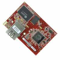
MODULE RABBITCORE RCM3315
Manufacturer
Rabbit Semiconductor
Datasheet
1.20-101-1068.pdf
(160 pages)
Specifications of 20-101-1068
Module/board Type
MPU Core Module
Product
Microcontroller Modules
Core Processor
Rabbit 3000
Clock Speed
44.2 MHz
Interface Type
Ethernet, Serial
Flash
512 KB
Timers
10 x 8 bit, 1 x 10 bit
Operating Supply Voltage
3.15 V to 3.45 V
Board Size
47 mm x 69 mm x 22 mm
Core
RCM3315
Processor Series
RCM3315
For Use With/related Products
RCM3315
Lead Free Status / RoHS Status
Lead free / RoHS Compliant
Other names
316-1114


Appendix B. Prototyping Board
Appendix C. LCD/Keypad Module
Appendix D. Power Supply
Appendix E. RabbitNet
Index
Schematics
User’s Manual
B.1 Introduction ........................................................................................................................................80
B.2 Mechanical Dimensions and Layout..................................................................................................83
B.3 Power Supply .....................................................................................................................................85
B.4 Using the Prototyping Board..............................................................................................................86
B.5 Prototyping Board Jumper Configurations ........................................................................................96
B.6 Use of Rabbit 3000 Parallel Ports ......................................................................................................98
C.1 Specifications ...................................................................................................................................101
C.2 Contrast Adjustments for All LCD/Keypad Modules......................................................................103
C.3 Keypad Labeling ..............................................................................................................................104
C.4 Header Pinouts .................................................................................................................................105
C.5 Mounting LCD/Keypad Module on the Prototyping Board ............................................................106
C.6 Bezel-Mount Installation..................................................................................................................107
C.7 Sample Programs .............................................................................................................................110
C.8 LCD/Keypad Module Function Calls ..............................................................................................111
D.1 Power Supplies.................................................................................................................................135
E.1 General RabbitNet Description ........................................................................................................139
E.2 Physical Implementation ..................................................................................................................141
E.3 Function Calls...................................................................................................................................142
B.1.1 Prototyping Board Features........................................................................................................81
B.4.1 Adding Other Components.........................................................................................................87
B.4.2 Digital I/O...................................................................................................................................88
B.4.3 CMOS Digital Outputs ...............................................................................................................89
B.4.4 Sinking Digital Outputs..............................................................................................................89
B.4.5 Relay Outputs .............................................................................................................................89
B.4.6 Serial Communication ................................................................................................................90
B.4.7 RabbitNet Ports ..........................................................................................................................93
B.4.8 Other Prototyping Board Modules .............................................................................................94
B.4.9 Quadrature Decoder ...................................................................................................................94
B.4.10 Stepper-Motor Control .............................................................................................................94
C.4.1 I/O Address Assignments.........................................................................................................105
C.6.1 Connect the LCD/Keypad Module to Your Prototyping Board...............................................109
C.8.1 LCD/Keypad Module Initialization..........................................................................................111
C.8.2 LEDs.........................................................................................................................................111
C.8.3 LCD Display.............................................................................................................................112
C.8.4 Keypad......................................................................................................................................132
D.1.1 Battery Backup.........................................................................................................................135
D.1.2 Battery-Backup Circuit ............................................................................................................136
D.1.3 Reset Generator .......................................................................................................................137
E.1.1 RabbitNet Connections.............................................................................................................139
E.1.2 RabbitNet Peripheral Cards ......................................................................................................140
E.2.1 Control and Routing .................................................................................................................141
E.3.1 Status Byte................................................................................................................................148
B.4.2.1 Digital Inputs ..................................................................................................................... 88
B.4.6.1 RS-232 ............................................................................................................................... 91
B.4.6.2 RS-485 ............................................................................................................................... 92
101
135
139
149
153
79
Related parts for 20-101-1068
Image
Part Number
Description
Manufacturer
Datasheet
Request
R

Part Number:
Description:
COMPUTER SGL-BRD BL2500 29.4MHZ
Manufacturer:
Rabbit Semiconductor
Datasheet:

Part Number:
Description:
COMPUTER SGL-BRD BL2500 29.4MHZ
Manufacturer:
Rabbit Semiconductor
Datasheet:

Part Number:
Description:
DISPLAY GRAPHIC 12KEY PROG OP670
Manufacturer:
Rabbit Semiconductor
Datasheet:
Part Number:
Description:
DISPLAY GRAPHIC 12KEY ETH OP6700
Manufacturer:
Rabbit Semiconductor
Datasheet:

Part Number:
Description:
COMPUTER SINGLE-BOARD BL2030
Manufacturer:
Rabbit Semiconductor
Part Number:
Description:
COMPUTER SGL-BOARD ETH BL2010
Manufacturer:
Rabbit Semiconductor

Part Number:
Description:
MODULE OP6810 W/O ETH/MEM EXPANS
Manufacturer:
Rabbit Semiconductor
Datasheet:
Part Number:
Description:
COMPUTER SINGLE-BOARD BL2020
Manufacturer:
Rabbit Semiconductor
Part Number:
Description:
COMPUTER BL2010 W/FRICTION LOCK
Manufacturer:
Rabbit Semiconductor
Part Number:
Description:
COMPUTER BL2020 W/FRICTION LOCK
Manufacturer:
Rabbit Semiconductor
Part Number:
Description:
COMPUTER SGL-BRD BL2500 44.2MHZ
Manufacturer:
Rabbit Semiconductor
Datasheet:
Part Number:
Description:
COMPUTER SGL-BOARD FULL BL2000
Manufacturer:
Rabbit Semiconductor

Part Number:
Description:
COMPUTER SINGLE-BOARD BL2110
Manufacturer:
Rabbit Semiconductor

Part Number:
Description:
COMPUTER SGL-BRD 29.4MHZ BL2610
Manufacturer:
Rabbit Semiconductor
Datasheet:
Part Number:
Description:
INTERFACE OP6800 512K FLASH&SRAM
Manufacturer:
Rabbit Semiconductor
Datasheet: