20-101-1196 Rabbit Semiconductor, 20-101-1196 Datasheet - Page 94
20-101-1196
Manufacturer Part Number
20-101-1196
Description
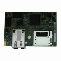
MODULE RABBITCORE RCM3900
Manufacturer
Rabbit Semiconductor
Datasheet
1.20-101-1196.pdf
(168 pages)
Specifications of 20-101-1196
Module/board Type
MPU Core Module
For Use With/related Products
RCM3900
Lead Free Status / RoHS Status
Lead free / RoHS Compliant
Other names
20-101-1196
316-1155
316-1155


B.4.2 Digital I/O
B.4.2.1 Digital Inputs
The Prototyping Board has four digital inputs, IN0–IN3, each of which is protected over a
range of –36 V to +36 V. The inputs are pulled up to +3.3 V as shown in Figure B-5.
W
W
Figure B-5. Prototyping Board Digital Inputs
The four quadrature decoder inputs on screw-terminal header J5 may be used as inputs
IN4–IN7. To use the PF0 signal from the Rabbit microprocessor, which goes to QD1B,
remember to reconfigure the jumper on header JP3 to jumper pins 1–2.
The actual switching threshold is between 0.9 V and 2.3 V. Anything below this value is a
logic 0, and anything above is a logic 1
.
The digital inputs are each fully protected over a range of -36 V to +36 V, and can handle
short spikes of ±40 V.
RabbitCore RCM3900 User’s Manual
94
Related parts for 20-101-1196
Image
Part Number
Description
Manufacturer
Datasheet
Request
R

Part Number:
Description:
COMPUTER SGL-BRD BL2500 29.4MHZ
Manufacturer:
Rabbit Semiconductor
Datasheet:

Part Number:
Description:
COMPUTER SGL-BRD BL2500 29.4MHZ
Manufacturer:
Rabbit Semiconductor
Datasheet:

Part Number:
Description:
DISPLAY GRAPHIC 12KEY PROG OP670
Manufacturer:
Rabbit Semiconductor
Datasheet:
Part Number:
Description:
DISPLAY GRAPHIC 12KEY ETH OP6700
Manufacturer:
Rabbit Semiconductor
Datasheet:

Part Number:
Description:
COMPUTER SINGLE-BOARD BL2030
Manufacturer:
Rabbit Semiconductor
Part Number:
Description:
COMPUTER SGL-BOARD ETH BL2010
Manufacturer:
Rabbit Semiconductor

Part Number:
Description:
MODULE OP6810 W/O ETH/MEM EXPANS
Manufacturer:
Rabbit Semiconductor
Datasheet:
Part Number:
Description:
COMPUTER SINGLE-BOARD BL2020
Manufacturer:
Rabbit Semiconductor
Part Number:
Description:
COMPUTER BL2010 W/FRICTION LOCK
Manufacturer:
Rabbit Semiconductor
Part Number:
Description:
COMPUTER BL2020 W/FRICTION LOCK
Manufacturer:
Rabbit Semiconductor
Part Number:
Description:
COMPUTER SGL-BRD BL2500 44.2MHZ
Manufacturer:
Rabbit Semiconductor
Datasheet:
Part Number:
Description:
COMPUTER SGL-BOARD FULL BL2000
Manufacturer:
Rabbit Semiconductor

Part Number:
Description:
COMPUTER SINGLE-BOARD BL2110
Manufacturer:
Rabbit Semiconductor

Part Number:
Description:
COMPUTER SGL-BRD 29.4MHZ BL2610
Manufacturer:
Rabbit Semiconductor
Datasheet:
Part Number:
Description:
INTERFACE OP6800 512K FLASH&SRAM
Manufacturer:
Rabbit Semiconductor
Datasheet: