20-101-0520 Rabbit Semiconductor, 20-101-0520 Datasheet - Page 4
20-101-0520
Manufacturer Part Number
20-101-0520
Description
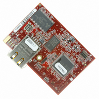
MODULE RABBITCORE RCM3200
Manufacturer
Rabbit Semiconductor
Datasheet
1.20-101-0522.pdf
(96 pages)
Specifications of 20-101-0520
Module/board Type
MPU Core Module
Product
Microcontroller Modules
Core Processor
Rabbit 3000
Clock Speed
44.2 MHz
Interface Type
Ethernet, Serial
Flash
512 KB
Timers
10 x 8 bit, 1 x 10 bit
Operating Supply Voltage
3.15 V to 3.45 V
Board Size
69 mm x 47 mm x 22 mm
Core
RCM3200
Processor Series
RCM3200
For Use With/related Products
RCM3200
Lead Free Status / RoHS Status
Lead free / RoHS Compliant
Other names
316-1097
Available stocks
Company
Part Number
Manufacturer
Quantity
Price
Company:

Part Number:
20-101-0520
Manufacturer:
Rabbit Semiconductor
Quantity:
1 879


Appendix B. Prototyping Board
Appendix C. LCD/Keypad Module
Appendix D. Power Supply
Appendix E. Programming Cable
Appendix F. Motor Control Option
Notice to Users
Index
Schematics
B.1 Mechanical Dimensions and Layout ................................................................................................. 36
B.2 Power Supply..................................................................................................................................... 37
B.3 Using the Prototyping Board ............................................................................................................. 38
C.1 Specifications..................................................................................................................................... 41
C.2 Contrast Adjustments for All Boards ................................................................................................ 43
C.3 Keypad Labeling................................................................................................................................ 44
C.4 Header Pinouts................................................................................................................................... 45
C.5 Mounting LCD/Keypad Module on the Prototyping Board.............................................................. 46
C.6 Bezel-Mount Installation ................................................................................................................... 47
C.7 LCD/Keypad Module Function APIs ................................................................................................ 50
C.8 Sample Programs............................................................................................................................... 70
D.1 Power Supplies .................................................................................................................................. 71
D.2 Optional +5 V Output........................................................................................................................ 72
F.1 Overview ............................................................................................................................................ 77
F.2 Header J6............................................................................................................................................ 78
F.3 Using Parallel Port F .......................................................................................................................... 79
F.4 PWM Outputs .................................................................................................................................... 82
F.5 PWM Registers .................................................................................................................................. 83
F.6 Quadrature Decoder ........................................................................................................................... 84
B.3.1 Adding Other Components ........................................................................................................ 39
B.3.2 Measuring Current Draw ........................................................................................................... 39
B.3.3 Other Prototyping Board Modules and Options ........................................................................ 39
C.4.1 I/O Address Assignments .......................................................................................................... 45
C.6.1 Connect the LCD/Keypad Module to Your Prototyping Board ................................................ 49
C.7.1 LEDs .......................................................................................................................................... 50
C.7.2 LCD Display .............................................................................................................................. 51
C.7.3 Keypad ....................................................................................................................................... 67
D.1.1 Battery-Backup Circuits ............................................................................................................ 71
D.1.2 Reset Generator ......................................................................................................................... 72
F.3.1 Parallel Port F Registers............................................................................................................. 79
RabbitCore RCM3200
35
41
71
73
77
87
89
91
Related parts for 20-101-0520
Image
Part Number
Description
Manufacturer
Datasheet
Request
R

Part Number:
Description:
COMPUTER SGL-BRD BL2500 29.4MHZ
Manufacturer:
Rabbit Semiconductor
Datasheet:

Part Number:
Description:
COMPUTER SGL-BRD BL2500 29.4MHZ
Manufacturer:
Rabbit Semiconductor
Datasheet:

Part Number:
Description:
DISPLAY GRAPHIC 12KEY PROG OP670
Manufacturer:
Rabbit Semiconductor
Datasheet:
Part Number:
Description:
DISPLAY GRAPHIC 12KEY ETH OP6700
Manufacturer:
Rabbit Semiconductor
Datasheet:

Part Number:
Description:
COMPUTER SINGLE-BOARD BL2030
Manufacturer:
Rabbit Semiconductor
Part Number:
Description:
COMPUTER SGL-BOARD ETH BL2010
Manufacturer:
Rabbit Semiconductor

Part Number:
Description:
MODULE OP6810 W/O ETH/MEM EXPANS
Manufacturer:
Rabbit Semiconductor
Datasheet:
Part Number:
Description:
COMPUTER SINGLE-BOARD BL2020
Manufacturer:
Rabbit Semiconductor
Part Number:
Description:
COMPUTER BL2010 W/FRICTION LOCK
Manufacturer:
Rabbit Semiconductor
Part Number:
Description:
COMPUTER BL2020 W/FRICTION LOCK
Manufacturer:
Rabbit Semiconductor
Part Number:
Description:
COMPUTER SGL-BRD BL2500 44.2MHZ
Manufacturer:
Rabbit Semiconductor
Datasheet:
Part Number:
Description:
COMPUTER SGL-BOARD FULL BL2000
Manufacturer:
Rabbit Semiconductor

Part Number:
Description:
COMPUTER SINGLE-BOARD BL2110
Manufacturer:
Rabbit Semiconductor

Part Number:
Description:
COMPUTER SGL-BRD 29.4MHZ BL2610
Manufacturer:
Rabbit Semiconductor
Datasheet:
Part Number:
Description:
INTERFACE OP6800 512K FLASH&SRAM
Manufacturer:
Rabbit Semiconductor
Datasheet: