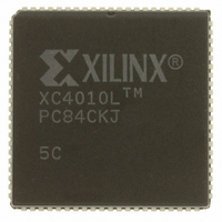
XC4010L-5PC84C Xilinx Inc, XC4010L-5PC84C Datasheet - Page 90

XC4010L-5PC84C
Manufacturer Part Number
XC4010L-5PC84C
Description
IC 3.3V FPGA 400 CLB'S 84-PLCC
Manufacturer
Xilinx Inc
Series
XC4000r
Datasheet
1.XC4005L-5PC84C.pdf
(175 pages)
Specifications of XC4010L-5PC84C
Number Of Logic Elements/cells
950
Number Of Labs/clbs
400
Total Ram Bits
12800
Number Of I /o
61
Number Of Gates
10000
Voltage - Supply
3 V ~ 3.6 V
Mounting Type
Surface Mount
Operating Temperature
0°C ~ 85°C
Package / Case
84-LCC (J-Lead)
Lead Free Status / RoHS Status
Contains lead / RoHS non-compliant
Other names
122-1123
Available stocks
Company
Part Number
Manufacturer
Quantity
Price
- Current page: 90 of 175
- Download datasheet (2Mb)
XC4000 Series Field Programmable Gate Arrays
XC4000E IOB Output Switching Characteristic Guidelines
Testing of the switching parameters is modeled after testing methods specified by MIL-M-38510/605. All devices are 100%
functionally tested. Internal timing parameters are not measured directly. They are derived from benchmark timing patterns
that are taken at device introduction, prior to any process improvements. For more detailed, more precise, and more up-to-
date information, use the values provided by the XACT timing calculator and used in the simulator. These values can be
printed in tabular format by running LCA2XNF -S.
The following guidelines reflect worst-case values over the recommended operating conditions. They are expressed in units
of nanoseconds and apply to all XC4000E devices unless otherwise noted.
Note 1:
Note 2:
4-94
Propagation Delays
(TTL Output Levels)
Clock (OK) to Pad, fast
Output (O) to Pad, fast
3-state to Pad hi-Z
3-state to Pad active
Propagation Delays
(CMOS Output Levels)
Clock (OK) to Pad, fast
Output (O) to Pad, fast
3-state to Pad hi-Z
3-state to Pad active
(slew-rate independent)
(slew-rate independent)
and valid, fast
and valid, fast
Description
Output timing is measured at pin threshold, with 50pF external capacitive loads (incl. test fixture). Slew-rate limited output
rise/fall times are approximately two times longer than fast output rise/fall times. For the effect of capacitive loads on ground
bounce, see the “Additional XC4000 Data” section of the Programmable Logic Data Book.
Voltage levels of unused pads, bonded or unbonded, must be valid logic levels. Each can be configured with the internal
pull-up (default) or pull-down resistor, or configured as a driven output, or can be driven from an external source.
slew-rate limited
slew-rate limited
slew-rate limited
slew-rate limited
slew-rate limited
slew-rate limited
Speed Grade
T
T
T
T
Symbol
T
T
T
T
T
T
OKPOFC
OKPOSC
T
T
TSONFC
TSONSC
T
T
OKPOF
OKPOS
TSONS
TSONF
TSHZC
OPSC
OPFC
TSHZ
OPF
OPS
Min
-4
Max
11.5
12.0
13.7
13.5
10.0
14.0
13.1
7.5
8.0
5.0
9.7
9.5
5.2
9.1
Min
-3
Max
11.1
11.6
13.4
11.4
6.5
9.5
5.5
8.5
4.2
8.1
7.8
9.7
4.3
7.6
Min
Preliminary
September 18, 1996 (Version 1.04)
-2
10.4
12.1
10.2
Max
4.5
7.0
4.8
7.3
3.8
7.3
9.8
7.0
8.7
3.9
6.8
Related parts for XC4010L-5PC84C
Image
Part Number
Description
Manufacturer
Datasheet
Request
R

Part Number:
Description:
IC 3.3V FPGA 400 CLB'S 208-PQFP
Manufacturer:
Xilinx Inc
Datasheet:

Part Number:
Description:
IC LOGIC CL ARRAY 10K GAT 208PQ
Manufacturer:
Xilinx Inc
Datasheet:

Part Number:
Description:
FPGA XC4000 Family 10K Gates 400 Cells 111MHz CMOS Technology 5V 160-Pin PQFP
Manufacturer:
Xilinx Inc

Part Number:
Description:
IC CPLD .8K 36MCELL 44-VQFP
Manufacturer:
Xilinx Inc
Datasheet:

Part Number:
Description:
IC CPLD 72MCRCELL 10NS 44VQFP
Manufacturer:
Xilinx Inc
Datasheet:

Part Number:
Description:
IC CPLD 1.6K 72MCELL 64-VQFP
Manufacturer:
Xilinx Inc
Datasheet:

Part Number:
Description:
IC CR-II CPLD 64MCELL 44-VQFP
Manufacturer:
Xilinx Inc
Datasheet:

Part Number:
Description:
IC CPLD 1.6K 72MCELL 100-TQFP
Manufacturer:
Xilinx Inc
Datasheet:

Part Number:
Description:
IC CR-II CPLD 64MCELL 56-BGA
Manufacturer:
Xilinx Inc
Datasheet:

Part Number:
Description:
IC CPLD 72MCRCELL 7.5NS 44VQFP
Manufacturer:
Xilinx Inc
Datasheet:

Part Number:
Description:
IC CR-II CPLD 64MCELL 100-VQFP
Manufacturer:
Xilinx Inc
Datasheet:

Part Number:
Description:
IC CPLD 1.6K 72MCELL 100-TQFP
Manufacturer:
Xilinx Inc
Datasheet:

Part Number:
Description:
IC CPLD 72MCRCELL 7.5NS 64VQFP
Manufacturer:
Xilinx Inc
Datasheet:

Part Number:
Description:
IC CPLD 1.6K 72MCELL 100-TQFP
Manufacturer:
Xilinx Inc
Datasheet:

Part Number:
Description:
IC CPLD 1.5K 64MCELL HP 44-VQFP
Manufacturer:
Xilinx Inc


