FCN-268M024-G/BD Fujitsu, FCN-268M024-G/BD Datasheet - Page 3
FCN-268M024-G/BD
Manufacturer Part Number
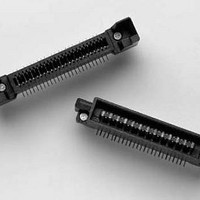
FCN-268M024-G/BD
Description
I/O Connectors PLUG 24 SIGNAL PAIRS 12mm STACK VERT SMT
Manufacturer
Fujitsu
Datasheet
1.FCN-268F036-G3DB.pdf
(16 pages)
Specifications of FCN-268M024-G/BD
Product
SMT Compact I/O Connectors
Number Of Positions / Contacts
48
Pitch
1.5 mm
Gender
Male
Mounting Style
Through Hole
Termination Style
Solder
Lead Free Status / Rohs Status
Lead free / RoHS Compliant


used to develop SPICE or other models and to
provide detailed data to the design community.
Typical high-frequency test boards designed by
Fujitsu include:
l
l
l
l
Differential pairs must be well-matched in
order to minimize skew and maintain the
proper impedance. Calibration lines of lengths
"L" (where L is the length of the test traces
between the article under test and the test
connectors) and 2L provide the opportunity to
calibrate out the board effects (if necessary)
as well as to make "reference" measurements
to test the goodness of an interconnect.
These reference measurements are especially
important when determining transmission
fidelity. Fujitsu Components attempts to use
standard, commonly available FR-4 type board
materials (better performers than some believe)
whenever possible; however, there are times
when so-called "low loss" board materials may
be required, such as for long paths running at
gigabit speeds.
In addition to very good test articles, test
equipment must be selected that will provide for
the measurements required at the bandwidths
needed. Measurements may be completed
for differential interconnects running at 100
Mbps, 625 Mbps, 1 Gbps, 2.5 Gbps or beyond
depending on the system being designed. Fujitsu
Components typically measures for single-ended
and differential impedance (using a "TDR"),
transmission fidelity, crosstalk, and eye pattern
performance among other measures of quality.
Typical transmission parameters quantified
well-controlled impedance, matched-Iength
test traces (with "real-world" widths and
spacings)
calibration/reference lines that mimic the test
traces
connector region entities (pads, pins, vias)
that reflect actual system board
implementations
low discontinuity test connectors (these give
access to the measurement equipment) of
sufficient bandwidth to meet the testing needs
(e.g. SMA, 55MB, etc.)
Specifications
subject to change
microGiGaCn
Dimensions are in millimeters (inches)
include signal edge and amplitude losses,
skews, propagation delays, and interconnect
bandwidth. At times, frequency domain data
(such as S-parameters) adds insight into these
measurements and may be preferred by some
customers. However, differential measurements
in the frequency domain must be approached
with caution and specialized knowledge.
TM
fCn-260 (D) Series
http://us.fujitsu.com/components
Related parts for FCN-268M024-G/BD
Image
Part Number
Description
Manufacturer
Datasheet
Request
R

Part Number:
Description:
Fujitsu Media Devices Limited [NMOS 1- CHANNEL, 13-BIT AND 3-CHANNEL, 6-BIT D/A CONVERTER]
Manufacturer:
Fujitsu
Datasheet:
Part Number:
Description:
Fujitsu Media Devices Limited [32-bit RISC Microcontroller]
Manufacturer:
Fujitsu
Datasheet:
Part Number:
Description:
Fujitsu Media Devices Limited [MOS 262,144 BIT DYNAMIC RANDOM ACCESS MEMORY]
Manufacturer:
Fujitsu
Datasheet:
Part Number:
Description:
Fujitsu Media Devices Limited [PROGRAMMABLE TIMER]
Manufacturer:
Fujitsu
Datasheet:
Part Number:
Description:
Fujitsu Media Devices Limited [MOS Universal Asynchronous receiver/transmitter(UART)]
Manufacturer:
Fujitsu
Datasheet:
Part Number:
Description:
Fujitsu Media Devices Limited [16M (2M X 8/1M X 16) BIT]
Manufacturer:
Fujitsu
Datasheet:
Part Number:
Description:
KIT, STARTER, MB95200/210/220
Manufacturer:
Fujitsu
Datasheet:
Part Number:
Description:
SWITCHING REGULATOR CONTROLLER
Manufacturer:
Fujitsu
Datasheet:
Part Number:
Description:
QUAD OPERATIONAL AMPLIFIER
Manufacturer:
Fujitsu
Datasheet:
Part Number:
Description:
Switching Regulator Controller (Switchable between push-pull and single-end functions)
Manufacturer:
Fujitsu
Datasheet:
Part Number:
Description:
HIGH-SPEED CMOS SINGLE CHIP 4-BIT MICROCOMPUTER MB88505HHIGH-SPEED CMOS SINGLE CHIP 4-BIT MICROCOMPUTER
Manufacturer:
Fujitsu
Datasheet:
Part Number:
Description:
MOS 1024 BIT NON VOLATILE RANDOM ACCESS MEMORY
Manufacturer:
Fujitsu
Datasheet:
Part Number:
Description:
Schottky TTL 2048-Bit Bipolar Programmable Read-Only Memory
Manufacturer:
Fujitsu
Datasheet:
Part Number:
Description:
QUAD COMPARATOR
Manufacturer:
Fujitsu
Datasheet: