JBXEA2G10FPSDS Souriau Connection Technology, JBXEA2G10FPSDS Datasheet - Page 3
JBXEA2G10FPSDS
Manufacturer Part Number
JBXEA2G10FPSDS
Description
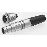
Circular Push Pull Connectors PUSH PULL
Manufacturer
Souriau Connection Technology
Series
JBXr
Datasheet
1.JBX2OUTLP09.pdf
(4 pages)
Specifications of JBXEA2G10FPSDS
Product Type
Connectors
Shell Style
Receptacle
Number Of Contacts
10


Contacts layouts
Note : Contact numbering mating faces receptacle view: counterclockwise from key at position 1
**Inserts with fixed non removable contacts
Male Insulator Wire Side
Male Insulator Wire Side
Male Insulator Wire Side
Solder
Crimp
PCB Straight Tails
PCB Right Angle*
Contact Diameter mm
Solder
Crimp
PCB Straight Tails*
PCB Right Angle*
Contact Diameter mm
Solder
Crimp
PCB Straight Tails*
PCB Right Angle*
Contact Diameter mm
Contact numbering mating faces plug view: clockwise from key at position 1
Shell size 00
Shell size 1
Shell size 0
Push Pull Connectors
04
S
0.5
02
S
C
1.3
02
S
C
P
Q
0.9
P
03
1.3
S
C
P
Q
03
* For receptacles with female contacts.
0.9
• Voltage Test Procedure
-
- The working voltage corresponds to the maximum voltage the connector is able to withstand
• Maximum current rating
- This indicated maximum current rating corresponds to the maximum current that can be ap-
Remark : If the current is applied on only one contact of the layout, then an increased current
value can be achieved over a long duration.
S
C
P
Q
The testing voltage corresponds to the maximum voltage the connector is able to withstand
in normal climatic conditions. The value is about 75% of the electrical breakdown voltage. The
testing voltage level can be reached several times in connectors life, but never applied for a con-
tinuous duration.
continuously during its life time, in real environmental conditions, even with high temperature.
The value is around 1/3 of the testing voltage
plied simultaneously on each line of the connector mated pair, continuously during its life
time, in normal climatic conditions.
0.9
S
C
P
Q
04
04
0.7
S**
C
P
Q
0.9
05
S
C
P
Q
05
Q
0.7
S**
C
P
S**
C
0.7
P
06
Q
0.5
06
P
S**
S**
C
0.7
07
P
.
Q
S**
0.7
07
S**
08
P
Q
C
P
0.5
0.5
S**
P
0.5
S**
10
P
08
12
S**
0.5
P
Options
• Protective boot
With each JBX connector, one protective
boot can accept diverse cable diameters
thus the end-user can manage various
cable diameters without bothering with
multiple part numbers.
• Caps : an efficient protection
against dust
KEYING
Keying angle
Receptacle
Plug
Push Pull Connectors
Part number
JBX BR3
JBX BR2
JBX BR0
JBX BR1
Receptacle Caps
JBX 00 MPN
0°
JBX 0 MP*
JBX 1 MP*
JBX 2 MP*
JBX 3 MP*
Color code
number
Part
A
B
G
J
M
N
R
V
O
* Color code - See chart below / In size 00, available only in black
Shell
Size
0
1
2
3
45°
Shell
size
00
0
1
3
2
Part number
Colors
blue
white
grey
yellow
brown
black
red
green
orange
JBX BF0
JBX BF1
JBX BF2
JBX BF3
JBX BF00
Plug Caps
Ø A
1.5
2.2
2.6
4
5
37.5°
Parts that require a protective boot
need to be ordered with an M
suffix. Protective boots are ordered
separately.
Dual Key Way
Material : ELASTOLLAN (PUR)
Working temperature :
- 40°C ; + 80°C
- 40°F ; + 176°F
Shell
Size
00
1
0
2
15
3
20
25
30
35
L
Dimensions
30°
1.5
3.5
4.9
min
1
2
Ø Cable
60°
max
3.5
5.5
7.5
9.7
12
Related parts for JBXEA2G10FPSDS
Image
Part Number
Description
Manufacturer
Datasheet
Request
R

Part Number:
Description:
CONN SEALING FOR WALL RCPT #22
Manufacturer:
Souriau Connection Technology
Part Number:
Description:
CONN SEALING FOR WALL RCPT #14
Manufacturer:
Souriau Connection Technology
Datasheet:

Part Number:
Description:
CONN RCPT SEALING CAP SIZE 10
Manufacturer:
Souriau Connection Technology
Datasheet:

Part Number:
Description:
CONN RCPT SEALING CAP SIZE 14
Manufacturer:
Souriau Connection Technology
Datasheet:

Part Number:
Description:
CONN STRAIN RELIEF 12POS
Manufacturer:
Souriau Connection Technology
Datasheet:

Part Number:
Description:
D38999 Series 3
Manufacturer:
Souriau Connection Technology
Datasheet: