75-068014-06S Amphenol, 75-068014-06S Datasheet - Page 247
75-068014-06S
Manufacturer Part Number
75-068014-06S
Description
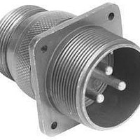
Circular MIL / Spec Connectors 6P 97 Series MIL-DTL-5015
Manufacturer
Amphenol
Series
97 Seriesr
Datasheet
1.M3902932-260.pdf
(436 pages)
Specifications of 75-068014-06S
Mil Type
MIL-DTL-5015
Product Type
Connectors
Contact Style
Socket (Female)
Shell Style
Receptacle
Shell Size
14S
Number Of Contacts
6
Insert Arrangement
14S-6
Mounting Style
Panel
Termination Style
Crimp
Contact Type
Socket
Shell Plating
Chromate over Cadmium, Olive Drab
Contact Plating
Silver
Voltage Rating
250 V
Body Material
Aluminum
Mounting Angle
Straight
Lead Free Status / Rohs Status
Lead free / RoHS Compliant


246
Contact Amphenol Aerospace for more information at 800-678-0141 • www.amphenol-aerospace.com
Insert Arrangement #16-26 / 17-26
Insert Arrangement #14-35 / 15-35
All dimensions for reference only. For alternate rotations see page 240 .
Note: Shown in this catalog are the most common insert patterns for PCB applications. For availability of other arrangements, consult Amphenol Corp., Sidney, NY.
Amphenol
Contact Locations
Front face of pin insert shown
Contact Locations
Front face of pin insert shown
Connector Type:
Insert Designation:
Connector Type:
Insert Designation:
Aerospace
N
M
P
L
a
Z
R
K
S
11
J
Y
b
MIL-DTL-38999
MIL-DTL-38999
H
T
X
A
c
Series II
Series II
31
14-35
G
NA
JT
JT
W
1
B
U
V
21
F
C
E
D
MIL-DTL-38999
MIL-DTL-38999
Circular Connectors – PCB Contacts
Insert Arrangements
Series I
Series I
17-26
15-35
LJT
LJT
Contact
Number
Number
Contact
MIL-DTL-38999
MIL-DTL-38999
G
M
A
B
C
D
E
F
H
K
L
N
P
J
10
11
12
13
14
15
16
17
18
19
20
Series III
Series III
1
2
3
4
5
6
7
8
9
Tri-Start
Tri-Start
Contact Hole Locations
17-26
15-35
Contact Hole Locations
X Axis
+.131
+.239
+.305
+.319
+.278
+.189
+.067
–.067
–.189
–.278
–.319
–.305
–.239
.000
X Axis
+.045
+.123
+.211
+.254
+.266
+.247
+.200
+.130
+.045
–.045
–.130
–.200
–.247
–.266
–.254
–.211
–.123
–.045
+.045
+.123
Location
Location
Number of
Number of
Contacts
Contacts
26
Y Axis
37
+.321
+.293
+.214
+.099
–.034
–.161
–.260
–.314
–.314
–.260
–.161
–.034
+.099
+.214
Y Axis
+.262
+.217
+.160
+.080
–.010
–.098
–.175
–.232
–.262
–.262
–.232
–.175
–.098
–.010
+.080
+.160
+.217
+.262
+.172
+.119
Contact
Contact
Size
Size
22D
20
Contact
Number
W
Contact
Number
R
S
U
V
X
Y
T
Z
a
b
c
21
22
23
24
25
26
27
28
29
30
31
32
33
34
35
36
37
Contact Hole Locations
Service
Service
Rating
Rating
Contact Hole Locations
M
I
X Axis
–.131
–.070
+.070
+.175
+.178
+.119
–.119
–.178
–.175
.000
.000
.000
X Axis
+.170
+.170
+.123
+.045
+.045
+.090
+.045
–.045
–.123
–.170
–.170
–.123
–.045
–.045
–.090
–.045
.000
Location
Location
Y Axis
+.293
+.177
+.177
+.094
–.036
–.151
–.203
–.151
–.036
+.094
+.065
–.065
Y Axis
+.040
–.050
–.127
–.172
–.172
–.127
–.050
+.040
+.119
+.172
+.074
–.004
–.082
–.082
–.004
+.074
–.004
Related parts for 75-068014-06S
Image
Part Number
Description
Manufacturer
Datasheet
Request
R

Part Number:
Description:
CBL BNC ST PLUG-PLG BEL 8218 36"
Manufacturer:
Amphenol Connex
Datasheet:
Part Number:
Description:
CBL BNC ST PLUG-PLG BEL 8218 24"
Manufacturer:
Amphenol Connex
Datasheet:
Part Number:
Description:
CBL BNC ST PLUG-PLG BEL 8218 12"
Manufacturer:
Amphenol Connex
Datasheet:
Part Number:
Description:
CBL BNC ST PLUG-PLUG BEL 8218 6"
Manufacturer:
Amphenol Connex
Datasheet:

Part Number:
Description:
CBL BNC ST PLUG-PLG BEL 8218 48"
Manufacturer:
Amphenol Connex
Datasheet:


Part Number:
Description:
Cable Specification: PU CABLE, UL20549 24AWG*8C+AD,OD= 6.0mm
Manufacturer:
Amphenol