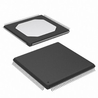
XCS10XL-4TQG144C Xilinx Inc, XCS10XL-4TQG144C Datasheet - Page 26

XCS10XL-4TQG144C
Manufacturer Part Number
XCS10XL-4TQG144C
Description
IC SPARTAN-XL FPGA 10K 144-TQFP
Manufacturer
Xilinx Inc
Series
Spartan™-XLr
Datasheet
1.XCS05XL-4VQG100C.pdf
(83 pages)
Specifications of XCS10XL-4TQG144C
Number Of Logic Elements/cells
466
Number Of Labs/clbs
196
Total Ram Bits
6272
Number Of I /o
112
Number Of Gates
10000
Voltage - Supply
3 V ~ 3.6 V
Mounting Type
Surface Mount
Operating Temperature
0°C ~ 85°C
Package / Case
144-LQFP
Lead Free Status / RoHS Status
Lead free / RoHS Compliant
Other names
122-1290
Available stocks
Company
Part Number
Manufacturer
Quantity
Price
Company:
Part Number:
XCS10XL-4TQG144C
Manufacturer:
XILINX
Quantity:
5 530
Company:
Part Number:
XCS10XL-4TQG144C
Manufacturer:
XILINX
Quantity:
345
Part Number:
XCS10XL-4TQG144C
Manufacturer:
XILINX/赛灵思
Quantity:
20 000
Spartan and Spartan-XL FPGA Families Data Sheet
During configuration, some of the I/O pins are used tempo-
rarily for the configuration process. All pins used during con-
figuration are shown in
Table 14: Pin Functions During Configuration
(Spartan Family Only)
26
Notes:
1.
2.
3.
Configuration Mode (MODE Pin)
PROGRAM (I)
Slave Serial
A shaded table cell represents the internal pull-up used
before and during configuration.
(I) represents an input; (O) represents an output.
INIT
HDC (High)
LDC (Low)
MODE (I)
CCLK (I)
DIN (I)
(High)
DONE
DOUT
TMS
TDO
TCK
INIT
TDI
is an open-drain output during configuration.
Table 14
PROGRAM (I)
Master Serial
HDC (High)
LDC (Low)
CCLK (O)
MODE (I)
DONE
DIN (I)
DOUT
(Low)
TMS
TDO
TCK
INIT
TDI
and
Table
15.
ALL OTHERS
PROGRAM
SGCK4-I/O
Operation
CCLK (I)
TMS-I/O
TDO-(O)
TCK-I/O
TDI-I/O
MODE
DONE
User
I/O
I/O
I/O
I/O
www.xilinx.com
Table 15: Pin Functions During Configuration
(Spartan-XL Family Only)
Notes:
1.
2.
3.
M1 (High) (I)
M0 (High) (I)
HDC (High)
PROGRAM
LDC (Low)
CCLK (I)
DONE
DIN (I)
DOUT
Slave
Serial
A shaded table cell represents the internal pull-up used
before and during configuration.
(I) represents an input; (O) represents an output.
INIT
[1:1]
TMS
TDO
TCK
INIT
TDI
CONFIGURATION MODE <M1:M0>
(I)
is an open-drain output during configuration.
M1 (High) (I)
M0 (Low) (I)
HDC (High)
PROGRAM
LDC (Low)
CCLK (O)
Master
DIN (I)
DONE
DOUT
Serial
[1:0]
TMS
TDO
TCK
INIT
TDI
(I)
HDC (High)
PROGRAM
M1(Low) (I)
LDC (Low)
DATA 7 (I)
DATA 6 (I)
DATA 5 (I)
DATA 4 (I)
DATA 3 (I)
DATA 2 (I)
DATA 1 (I)
DATA 0 (I)
Express
CCLK (I)
DS060 (v1.8) June 26, 2008
DONE
DOUT
M0 (I)
[0:X]
TMS
TDO
TCK
CS1
INIT
TDI
(I)
Product Specification
PROGRAM
Operation
GCK6-I/O
OTHERS
CCLK (I)
TDO-(O)
TCK-I/O
TMS-I/O
TDI-I/O
DONE
User
ALL
M1
M0
I/O
I/O
I/O
I/O
I/O
I/O
I/O
I/O
I/O
I/O
I/O
I/O
R


