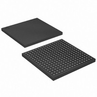
XC2S50E-6FTG256C Xilinx Inc, XC2S50E-6FTG256C Datasheet - Page 22

XC2S50E-6FTG256C
Manufacturer Part Number
XC2S50E-6FTG256C
Description
IC SPARTAN-IIE FPGA 50K 256FTBGA
Manufacturer
Xilinx Inc
Series
Spartan™-IIEr
Datasheet
1.XC2S50E-6TQG144C.pdf
(108 pages)
Specifications of XC2S50E-6FTG256C
Number Of Logic Elements/cells
1728
Number Of Labs/clbs
384
Total Ram Bits
32768
Number Of I /o
182
Number Of Gates
50000
Voltage - Supply
1.71 V ~ 1.89 V
Mounting Type
Surface Mount
Operating Temperature
0°C ~ 85°C
Package / Case
256-LBGA
Lead Free Status / RoHS Status
Lead free / RoHS Compliant
Other names
122-1328
Available stocks
Company
Part Number
Manufacturer
Quantity
Price
Company:
Part Number:
XC2S50E-6FTG256C
Manufacturer:
ISSI
Quantity:
1 001
Part Number:
XC2S50E-6FTG256C
Manufacturer:
XILINX/赛灵思
Quantity:
20 000
Spartan-IIE FPGA Family: Functional Description
Table 11: Configuration Modes
Signals
There are two kinds of pins that are used to configure
Spartan-IIE devices: Dedicated pins perform only specific
configuration-related functions; the other pins can serve as
general purpose I/Os once user operation has begun.
The dedicated pins comprise the mode pins (M2, M1, M0),
the configuration clock pin (CCLK), the PROGRAM pin, the
DONE pin and the boundary-scan pins (TDI, TDO, TMS,
TCK). Depending on the selected configuration mode,
CCLK may be an output generated by the FPGA, or may be
generated externally, and provided to the FPGA as an input.
Note that some configuration pins can act as outputs. For
correct operation, these pins require a V
an LVTTL signal or 2.5V to drive an LVCMOS signal. All the
relevant pins fall in banks 2 or 3. The CS and WRITE pins
for Slave Parallel mode are located in bank 1.
For a more detailed description than that given below, see
Module 1
the Spartan-II and Spartan-IIE FPGA Families.
The Process
The sequence of steps necessary to configure Spartan-IIE
devices are shown in
divided into three different phases.
•
•
22
Notes:
1.
2.
Master Serial mode
Slave Parallel mode
(SelectMAP)
Boundary-Scan mode
Slave Serial mode
Configuration Mode
Initiating configuration
Configuration memory clear
During power-on and throughout configuration, the I/O drivers will be in a high-impedance state. After configuration, all unused I/Os
(those not assigned signals) will remain in a high-impedance state. Pins used as outputs may pulse High at the end of configuration
(see
If the Mode pins are set for preconfiguration pull-ups, those resistors go into effect once the rising edge of INIT samples the Mode
pins. They will stay in effect until GTS is released during startup, after which the UnusedPin bitstream generator option will determine
whether the unused I/Os have a pull-up, pull-down, or no resistor.
Answer
and XAPP176, Configuration and Readback of
10504).
Figure
Preconfiguration
16. The overall flow can be
Pull-ups
Yes
Yes
Yes
Yes
No
No
No
No
CCO
of 3.3V to drive
M0
0
0
0
0
1
1
1
1
www.xilinx.com
M1
0
0
1
1
0
0
1
1
M2
•
•
The memory clearing and start-up phases are the same for
all configuration modes; however, the steps for the loading
of data frames are different. Thus, the details for data frame
loading are described separately in the sections devoted to
each mode.
Initiating Configuration
There are two different ways to initiate the configuration pro-
cess: applying power to the device or asserting the PRO-
GRAM input.
Configuration on power-up occurs automatically unless it is
delayed by the user, as described in a separate section
below. The waveform for configuration on power-up is
shown in
Before configuration can begin, V
greater than 1.0V. Furthermore, all V
be connected to a 1.8V supply. For more information on
delaying configuration, see
page
Once in user operation, the device can be re-configured
simply by pulling the PROGRAM pin Low. The device
acknowledges the beginning of the configuration process by
driving DONE Low, then enters the memory-clearing phase.
0
1
0
1
0
1
0
1
Loading data frames
Start-up
23.
Direction
Configuration Switching Characteristics, page
CCLK
N/A
Out
In
In
Data Width
Clearing Configuration Memory,
1
8
1
1
DS077-2 (v2.3) June 18, 2008
CCO
CCINT
Product Specification
Bank 2 must be
power pins must
Serial D
Yes
Yes
No
No
OUT
48.
R


