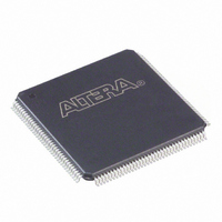
EPF10K10TC144-3N Altera, EPF10K10TC144-3N Datasheet - Page 124

EPF10K10TC144-3N
Manufacturer Part Number
EPF10K10TC144-3N
Description
IC FLEX 10K FPGA 10K 144-TQFP
Manufacturer
Altera
Series
FLEX-10K®r
Datasheet
1.EPF10K10ATC100-3.pdf
(128 pages)
Specifications of EPF10K10TC144-3N
Number Of Logic Elements/cells
576
Number Of Labs/clbs
72
Total Ram Bits
6144
Number Of I /o
102
Number Of Gates
31000
Voltage - Supply
4.75 V ~ 5.25 V
Mounting Type
Surface Mount
Operating Temperature
0°C ~ 85°C
Package / Case
144-TQFP, 144-VQFP
Lead Free Status / RoHS Status
Lead free / RoHS Compliant
Other names
544-2200
Available stocks
Company
Part Number
Manufacturer
Quantity
Price
Part Number:
EPF10K10TC144-3N
Manufacturer:
ALTERA/阿尔特拉
Quantity:
20 000
Configuration &
Operation
124
FLEX 10K Embedded Programmable Logic Device Family Data Sheet
f
Figure 32. I
The FLEX 10K architecture supports several configuration schemes. This
section summarizes the device operating modes and available device
configuration schemes.
See Application Note 116 (Configuring APEX 20K, FLEX 10K & FLEX 6000
Devices) for detailed descriptions of device configuration options, device
configuration pins, and for information on configuring FLEX 10K devices,
including sample schematics, timing diagrams, and configuration
parameters.
Operating Modes
The FLEX 10K architecture uses SRAM configuration elements that
require configuration data to be loaded every time the circuit powers up.
The process of physically loading the SRAM data into the device is called
configuration. Before configuration, as VCC rises, the device initiates a
Power-On Reset (POR). This POR event clears the device and prepares it
for configuration. The FLEX 10K POR time does not exceed 50 s.
During initialization, which occurs immediately after configuration, the
device resets registers, enables I/O pins, and begins to operate as a logic
device. The I/O pins are tri-stated during power-up, and before and
during configuration. Together, the configuration and initialization
processes are called command mode; normal device operation is called user
mode.
CCACTIVE
EPF10K250A
I
Current (mA)
CC
Supply
vs. Operating Frequency (Part 3 of 3)
3,500
3,000
2,500
2,000
1,500
1,000
500
0
20
Frequency (MHz)
40
60
80
Altera Corporation
100


