ULR3R001FLFTR IRC, ULR3R001FLFTR Datasheet - Page 4
ULR3R001FLFTR
Manufacturer Part Number
ULR3R001FLFTR
Description
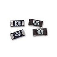
Current Sense Resistors - SMD 3W 0.001 OHM 1%
Manufacturer
IRC
Series
ULRr
Datasheet
1.ULR1R0015JLF.pdf
(6 pages)
Specifications of ULR3R001FLFTR
Resistance
0.001 Ohms
Power Rating
3 Watts
Tolerance
1 %
Temperature Coefficient
+/- 50 PPM / C
Package / Case
2512 (6332 metric)
Product
Metal Element Current Sensing Resistors
Operating Temperature Range
- 55 C to + 170 C
Dimensions
3.2 mm W x 6.3 mm L x 0.6 mm H
Termination Style
SMD/SMT
Lead Free Status / Rohs Status
Lead free / RoHS Compliant


Wire and Film Technologies Division
Telephone: 361 992 7900 • Facsimile: 361 992 3377 • Website: www.irctt.com
Construction
Plastic Tape Speci cation
Power Derating Curve
2512
2010
1206
Size
Note:
1.
2.
3.
4.
5.
Black Type
A low TCR resistance alloy plate with plated connection
bands is protectively coated and numerically marked with
the resistance value, as described in Product Marking. This
version has standard plated connection and is suitable for
wave or IR re ow soldering processes.
100
0
The cumulative tolerance of 10 sprocket hole pitch is ± 0.2 mm.
Carrier camber shall not be more than 1 mm per 100 mm through a length of 250 mm.
A & B measured 0.3 mm from the bottom of the packet.
T measured at a point on the inside bottom of the packet to the top surface of the carrier.
Pocket position relative to sprocket hole is measured as the true position of the pocket and not the pocket hole.
50
Resistance
0
0
0.5 - 7
1 - 10
1 - 10
(mΩ)
5 .
-
Ambient Temperature (°C)
2
0
Emboss Tape
3.4±0.1
2.85±0.1
1.9
T
±0.1
A
85
Top Tape
6.73±0.1
6
5.55±0.1
3.6
7 .
Resistor
5
±0.1
B
±
0
1 .
12±0.1
12±0.1
8
±0.2
W
• 4222 South Staples Street • Corpus Christi Texas 78411 USA
170
A
1.75±0.1
1.75±0.1
1.75±0.1
B
ψ D
E
0
P
1
5.5±0.05
5.5±0.05
3.5±0.05
P
F
Note:
The power derating curve is a guidance based on a
conservative design model. The ULR is a solid metal
alloy construction that can withstand signi cantly greater
operating temperatures than the conservative model
permits. The protective coating will operate up to
260°C and the alloy can withstand in excess of 350°C.
Therefore, the system thermal design will be a more
signi cant design parameter due to the heat limitations of
the solder joint.
2
Green Type
A low TCR alloy plate is grooved to set the nal resistance.
The lower faces are solder plated for connections, and the top
surface is protectively coated and numerically marked with the
resistance value, as described in Product Marking. This part
is suitable for wave and IR re ow soldering processes. Wave
re ow requires the solder mask to be dimensioned according to
page 2 using the W and D dimensions of the part.
P
0
4±0.1 4±0.1 2±0.05
4±0.1 4±0.1 2±0.05 1.55±0.05
4±0.1 4±0.1 2±0.05 1.55±0.05
P 0
direction of unreeling
P 1
E
F
P 2
W
1.5+0.1, -0 1.4 min. 0.81±0.1
1
ψ D
5 .
Φ D 0
+
. 0
ULR Issue April 2011 Sheet 4 of 6
1
, 1
1.4Min.
0 -
1
1.4 min. 0.85±0.1
1.0 min. 0.87±0.1
4 .
Φ D 1
m
i
. n
0
8 .
0
T
±
0
1 .
Related parts for ULR3R001FLFTR
Image
Part Number
Description
Manufacturer
Datasheet
Request
R

Part Number:
Description:
Day/night Infrared Led Camera ? Up To 164 Feet 50m
Manufacturer:
American Accurate Components
Datasheet:

Part Number:
Description:
Power MOSFET(Vdss=200V/ Rds(on)=0.40ohm/ Id=9.0A)
Manufacturer:
International Rectifier
Datasheet:
Part Number:
Description:
Miniatur-ir-temperatursensoren Abgesetzter Elektronik
Manufacturer:
ETC-unknow
Datasheet:
Part Number:
Description:
Infrarot-Temperatur-Messgerat
Manufacturer:
ASM-SENSOR [ASM GmbH]
Datasheet:
Part Number:
Description:
Miniatur-IR-Temperatursensoren mit abgesetzter Elektronik
Manufacturer:
ASM-SENSOR [ASM GmbH]
Datasheet:
Part Number:
Description:
IRC
Manufacturer:
International Resistive Company (IRC)
Part Number:
Description:
IRC
Manufacturer:
International Resistive Company (IRC)
Part Number:
Description:
IRC
Manufacturer:
International Resistive Company (IRC)
Part Number:
Description:
IRC
Manufacturer:
International Resistive Company (IRC)
Part Number:
Description:
IRC
Manufacturer:
International Resistive Company (IRC)
Part Number:
Description:
IRC
Manufacturer:
International Resistive Company (IRC)
Part Number:
Description:
IRC
Manufacturer:
International Resistive Company (IRC)
Part Number:
Description:
IRC
Manufacturer:
International Resistive Company (IRC)
Part Number:
Description:
IRC
Manufacturer:
International Resistive Company (IRC)
Part Number:
Description:
IRC
Manufacturer:
International Resistive Company (IRC)