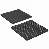
EPM7512BBC256-10 Altera, EPM7512BBC256-10 Datasheet - Page 33

EPM7512BBC256-10
Manufacturer Part Number
EPM7512BBC256-10
Description
IC MAX 7000 CPLD 512 256-BGA
Manufacturer
Altera
Series
MAX® 7000Br
Datasheet
1.EPM7256BFC256-7.pdf
(66 pages)
Specifications of EPM7512BBC256-10
Programmable Type
In System Programmable
Delay Time Tpd(1) Max
10.0ns
Voltage Supply - Internal
2.375 V ~ 2.625 V
Number Of Logic Elements/blocks
32
Number Of Macrocells
512
Number Of Gates
10000
Number Of I /o
212
Operating Temperature
0°C ~ 70°C
Mounting Type
Surface Mount
Package / Case
256-BGA
Voltage
2.5V
Memory Type
EEPROM
Number Of Logic Elements/cells
32
Lead Free Status / RoHS Status
Contains lead / RoHS non-compliant
Features
-
Available stocks
Company
Part Number
Manufacturer
Quantity
Price
Company:
Part Number:
EPM7512BBC256-10
Manufacturer:
CY
Quantity:
143
Timing Model
Figure 13. MAX 7000B Timing Model
Altera Corporation
Delay
Input
t
I N
f
Delay
t
PIA
PIA
MAX 7000B device timing can be analyzed with the Altera software, with
a variety of popular industry-standard EDA simulators and timing
analyzers, or with the timing model shown in
devices have predictable internal delays that enable the designer to
determine the worst-case timing of any design. The Altera software
provides timing simulation, point-to-point delay prediction, and detailed
timing analysis for device-wide performance evaluation.
The timing characteristics of any signal path can be derived from the
timing model and parameters of a particular device. External timing
parameters, which represent pin-to-pin timing delays, can be calculated
as the sum of internal parameters.
between internal and external delay parameters.
See
information.
Application Note 94 (Understanding MAX 7000 Timing)
Expander Delay
Internal Output
Global Control
Control Delay
Enable Delay
Logic Array
Register
Shared
Delay
Delay
t
t
t
t
t
t
t
GLOB
SEXP
LAC
I C
EN
IOE
LAD
Expander Delay
MAX 7000B Programmable Logic Device Data Sheet
Parallel
t
PEXP
Input Delay
t
F I N
Figure 14
Fast
t
F I N
+
t
F I N D
Register
t
t
t
t
t
t
t
t
Delay
SU
H
PRE
CLR
RD
COMB
FSU
FH
shows the timing relationship
Figure
Output
Delay
t
t
t
t
t
t
t
OD1
OD2
OD3
XZ
Z
Z X2
Z X3
13. MAX 7000B
X1
for more
Delay
I/O
t
I O
33


