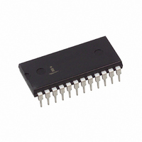
HI3-DAC80V-5 Intersil, HI3-DAC80V-5 Datasheet - Page 3

HI3-DAC80V-5
Manufacturer Part Number
HI3-DAC80V-5
Description
CONV D/A 12BIT OUTPUT AMP 24PDIP
Manufacturer
Intersil
Datasheet
1.HI3-DAC80V-5.pdf
(8 pages)
Specifications of HI3-DAC80V-5
Settling Time
1.5µs
Number Of Bits
12
Data Interface
Parallel
Number Of Converters
1
Voltage Supply Source
Dual ±
Operating Temperature
0°C ~ 75°C
Mounting Type
Through Hole
Package / Case
24-DIP (0.600", 15.24mm)
Lead Free Status / RoHS Status
Contains lead / RoHS non-compliant
Power Dissipation (max)
-
Available stocks
Company
Part Number
Manufacturer
Quantity
Price
Company:
Part Number:
HI3-DAC80V-5
Manufacturer:
Intersil
Quantity:
30
Company:
Part Number:
HI3-DAC80V-5
Manufacturer:
HARRIS
Quantity:
102
Part Number:
HI3-DAC80V-5
Manufacturer:
HAR
Quantity:
20 000
Absolute Maximum Ratings
Power Supply Inputs
Reference
Digital Inputs (Bits 1 to 12). . . . . . . . . . . . . . . . . . . . . . . . -1V to +V
Operating Conditions
Temperature Range . . . . . . . . . . . . . . . . . . . . . . . . . . . . 0
CAUTION: Stresses above those listed in “Absolute Maximum Ratings” may cause permanent damage to the device. This is a stress only rating and operation of the
device at these or any other conditions above those indicated in the operational sections of this specification is not implied.
NOTE:
Electrical Specifications
SYSTEM PERFORMANCE
Resolution
ACCURACY (Note 3)
Linear Error
Differential Linearity Error
Monotonicity
Gain Error
Offset Error
ANALOG OUTPUT
Output Ranges (See Figure 2 and
Table 2)
Output Current
Output Resistance
Short Circuit Duration
DRIFT (Note 3)
Total Bipolar Drift (Includes Gain,
Offset and Linearity Drifts)
Total Error
Gain
1.
+V
-V
Input (Pin 16) . . . . . . . . . . . . . . . . . . . . . . . . . . . . . . . . . . . . . +V
Output Drain . . . . . . . . . . . . . . . . . . . . . . . . . . . . . . . . . . . . 2.5mA
S
Unipolar
Bipolar
S
JA
. . . . . . . . . . . . . . . . . . . . . . . . . . . . . . . . . . . . . . . . . . . . +20V
. . . . . . . . . . . . . . . . . . . . . . . . . . . . . . . . . . . . . . . . . . . . . -20V
is measured with the component mounted on a low effective thermal conductivity test board in free air. See Tech Brief TB379 for details.
PARAMETER
3
T
A
= 25
Full Temperature
Full Temperature
Full Temperature
Full Temperature (Notes 2, 4)
Full Temperature (Note 2)
To Common
Full Temperature
Full Temperature (Note 6)
Full Temperature (Note 6)
With Internal Reference
Without Internal Reference
o
C, V
TEST CONDITIONS
S
12V to 15V (Note 5), Pin 16 Shorted to Pin 24, Unless Otherwise Specified
o
C to 75
HI-DAC80V
o
C
S
S
Thermal Information
Thermal Resistance (Typical, Note 1)
Maximum Power Dissipation
Maximum Junction Temperature . . . . . . . . . . . . . . . . . . . . . . 150
Maximum Storage Temperature Range . . . . . . . . . . -65
Maximum Lead Temperature (Soldering 10s) . . . . . . . . . . . . 300
Die Characteristics
Process . . . . . . . . . . . . . . . . . . . . . . . . . . . . . . . . . . . . . . . Bipolar-DI
Transistor Count. . . . . . . . . . . . . . . . . . . . . . . . . . . . . . . . . . . . . . 214
PDIP Package . . . . . . . . . . . . . . . . . . . . . . . . . . . . .
PDIP Package . . . . . . . . . . . . . . . . . . . . . . . . . . . . . . . . . 550mW
MIN
-
-
-
-
-
-
-
-
-
-
-
-
-
-
-
5
Guaranteed
Continuous
0 to 10
0 to 5
TYP
0.05
0.05
0.08
0.06
0.1
2.5
1
1
10
15
-
-
-
5
7
/
/
4
2
MAX
0.15
0.15
12
0.3
0.1
1
3
20
30
-
-
-
-
-
-
-
-
/
/
2
4
ppm/
ppm/
ppm/
o
% FSR
% FSR
% FSR
% FSR
UNITS
C to 150
LSB
LSB
Bits
mA
JA
V
V
V
V
V
-
o
o
o
(
55
o
C
C
C
C/W)
o
o
o
C
C
C


