IM-6RFCS-40 22 10% Vishay, IM-6RFCS-40 22 10% Datasheet
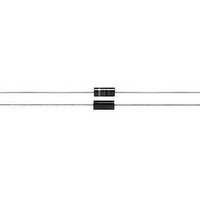
RF Inductors 22uH 10%

IM-6RFCS-40 22 10%

Manufacturer Part Number
IM-6RFCS-40 22 10%
Description
RF Inductors 22uH 10%
Manufacturer
Vishay
Datasheet

Specifications of IM-6RFCS-40 22 10%

Inductance
22 uH
Tolerance
10 %
Maximum Dc Current
430 mAmps
Maximum Dc Resistance
1.8 Ohms
Self Resonant Frequency
32 MHz
Q Minimum
75
Operating Temperature Range
- 55 C to + 125 C
Termination Style
Axial
Dimensions
11.35 mm L
Lead Free Status / Rohs Status
Lead free / RoHS Compliant
ELECTRICAL SPECIFICATIONS
Inductance Tolerance: ± 10 % on Q-meter for 0.10 μH to
22 μH, ± 5 % 1000 cps bridge for 27 μH to 100 μH, ± 5 %
on Q-meter for 120 μH to 1000 μH
Note
• L and Q are not always tested at the same frequency, inductance
Dielectric Strength: 700 V
Operating Temperature: - 55 °C to + 125 °C
Self-Resonant Frequency: Minimum SRF measured with
full length leads on grid-dip meter
Q: Measured on Q-meter
DENSITY SPECIFICATIONS
Weight: 0.9 g maximum
Note
(1)
Document Number: 34034
Revision: 15-Jul-09
DIMENSIONS in inches [millimeters]
STANDARD ELECTRICAL SPECIFICATIONS
MODEL
IM-6RFCS-40
IM-6RFCS-40
IM-6RFCS-40
IM-6RFCS-40
IM-6RFCS-40
IM-6RFCS-40
IM-6RFCS-40
IM-6RFCS-40
IM-6RFCS-40
IM-6RFCS-40
IM-6RFCS-40
IM-6RFCS-40
IM-6RFCS-40
IM-6RFCS-40
IM-6RFCS-40
IM-6RFCS-40
IM-6RFCS-40
values that are tested on Q-meter, are tested at standard test
frequencies
Model electricals and tolerances shown
(1)
Inductors, Commercial, Molded, Axial Leaded
IND.
(μH)
0.10
0.12
0.15
0.18
0.22
0.27
0.33
0.39
0.47
0.56
0.68
0.82
1.0
1.2
1.5
1.8
2.2
RMS
at sea level
TOL.
± 10
± 10
± 10
± 10
± 10
± 10
± 10
± 10
± 10
± 10
± 10
± 10
± 10
± 10
± 10
± 10
± 10
(%)
For technical questions, contact:
# 22 0.025 ± 0.002
[0.635 ± 0.051]
MIN.
1.30 [33.02]
75
75
75
75
75
70
70
65
60
55
55
50
50
45
45
45
45
Q
Typ. Min.
TCW
TEST FREQUENCY
[11.35 ± 0.254]
0.440 ± 0.010
(MHz)
50
50
50
50
50
45
40
40
25
25
25
25
20
20
15
15
15
FEATURES
• Classification is grade 1, class B
• Inductance range is 0.10 μH to 1000 μH
• Proven reliability molded inductors
• Compliant to RoHS directive 2002/95/EC
MECHANICAL SPECIFICATIONS
Terminal Strength: Meets 5 lb pull per MIL-PRF-15305
(latest revision)
ENVIRONMENTAL SPECIFICATIONS
Moisture and Shock Resistance: Meets requirements of
MIL-PRF-15305, grade 1, class B
Vibration: High frequency, 10 Hz to 2000 Hz at 20 g ± 10 %
maximum for 12 logarythmic swings, each of 20 min
duration repeated for each of three mutually perpendicular
planes
magnetics@vishay.com
0.190 ± 0.010
[4.83 ± 0.254]
SRF MIN.
(MHz)
400
400
400
400
400
376
352
320
288
264
240
220
200
176
160
144
132
DCR MAX.
0.025
0.02
0.03
0.03
0.03
0.04
0.05
0.08
0.08
0.10
0.12
0.18
0.24
0.35
0.43
0.65
0.80
(Ω)
IM-6-RFCS-40
RATED DC CURRENT
Vishay Dale
4000
3500
3000
3000
3000
2700
2500
2000
2000
1700
1500
1300
1100
1000
850
720
610
www.vishay.com
(mA)
1

Related parts for IM-6RFCS-40 22 10%

IM-6RFCS-40 22 10% Summary of contents

Page 1

... Terminal Strength: Meets 5 lb pull per MIL-PRF-15305 (latest revision) ENVIRONMENTAL SPECIFICATIONS Moisture and Shock Resistance: Meets requirements of MIL-PRF-15305, grade 1, class B Vibration: High frequency 2000 ± maximum for 12 logarythmic swings, each of 20 min duration repeated for each of three mutually perpendicular planes 1.30 [33.02] Typ. Min. 0.190 ± 0.010 # 22 0.025 ± ...

Page 2

... IM-6RFCS-40 120 ± 5 IM-6RFCS-40 150 ± 5 IM-6RFCS-40 180 ± 5 IM-6RFCS-40 220 ± 5 IM-6RFCS-40 270 ± 5 IM-6RFCS-40 300 ± 5 IM-6RFCS-40 330 ± 5 IM-6RFCS-40 360 ± 5 IM-6RFCS-40 390 ± 5 IM-6RFCS-40 430 ± 5 IM-6RFCS-40 470 ± 5 IM-6RFCS-40 510 ± 5 IM-6RFCS-40 560 ± 5 ...

Page 3

... Please contact authorized Vishay personnel to obtain written terms and conditions regarding products designed for such applications. No license, express or implied, by estoppel or otherwise, to any intellectual property rights is granted by this document or by any conduct of Vishay. Product names and markings noted herein may be trademarks of their respective owners. ...

Related keywords