1N5819HW-7-F Diodes Zetex, 1N5819HW-7-F Datasheet
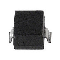
1.0A SURFACE MOUNT SCHOTTKY

1N5819HW-7-F

Manufacturer Part Number
1N5819HW-7-F
Description
1.0A SURFACE MOUNT SCHOTTKY
Manufacturer
Diodes Zetex
Datasheet

Specifications of 1N5819HW-7-F

Rectifier Type
Schottky Diode
Configuration
Single
Peak Rep Rev Volt
40V
Avg. Forward Curr (max)
1A
Rev Curr
1000uA
Peak Non-repetitive Surge Current (max)
25A
Forward Voltage
0.75@3AV
Operating Temp Range
-65C to 125C
Package Type
SOD-123
Operating Temperature Classification
Military
Mounting
Surface Mount
Pin Count
2
Lead Free Status / Rohs Status
Compliant

Available stocks

Company
Part Number
Manufacturer
Quantity
Price
Part Number:
1N5819HW-7-F
Manufacturer:
MICROCHIP
Quantity:
1 000
Part Number:
1N5819HW-7-F
Manufacturer:
KEL
Quantity:
400
Part Number:
1N5819HW-7-F
Manufacturer:
DIODES
Quantity:
8 000
Part Number:
1N5819HW-7-F
Manufacturer:
DIODES
Quantity:
120
Part Number:
1N5819HW-7-F
Manufacturer:
DIODES/美台
Quantity:
20 000
Company:
Part Number:
1N5819HW-7-F
Quantity:
9 000
Company:
Part Number:
1N5819HW-7-F
Quantity:
215
Company:
Part Number:
1N5819HW-7-F
Quantity:
10 000
Company:
Part Number:
1N5819HW-7-F
Quantity:
10 000
Single phase, half wave, 60Hz, resistive or inductive load.
For capacitance load, derate current by 20%.
Thermal Characteristics
Electrical Characteristics
Maximum Ratings
Features
Peak Repetitive Reverse Voltage
Working Peak Reverse Voltage
DC Blocking Voltage
RMS Reverse Voltage
Average Rectified Output Current
Repetitive Peak Forward Current
t
Non-Repetitive Peak Forward Surge Current 8.3ms
Single Half Sine-Wave Superimposed on Rated Load
Power Dissipation (Note 2)
Typical Thermal Resistance Junction to Ambient (Note 2)
Operating and Storage Temperature Range
Reverse Breakdown Voltage (Note 3)
Forward Voltage
Reverse Leakage Current (Note 3)
Total Capacitance
p ≤
Notes:
1N5819HW
Document number: DS30217 Rev. 15 - 2
1ms, δ ≤ 0.5
Guard Ring Die Construction for Transient Protection
Low Power Loss, High Efficiency
High Surge Capability
High Current Capability and Low Forward Voltage Drop
For Use in Low Voltage, High Frequency Inverters, Free
Wheeling, and Polarity Protection Application
Lead, Halogen and Antimony Free, RoHS Compliant (Note 1)
"Green" Device (Note 4)
1. No purposefully added lead. Halogen and Antimony Free.
2. Device mounted on FR-4 PC Board, 2"x2", 2 oz. Copper, single sided, Cathode pad dimensions 0.75"x1.0", Anode pad dimensions 0.25"x1.0".
3. Short duration pulse test used to minimize self-heating effect.
4. Product manufactured with Data Code V9 (week 33, 2008) and newer are built with Green Molding Compound. Product manufactured prior to Date
Code V9 are built with Non-Green Molding Compound and may contain Halogens or Sb
Characteristic
Characteristic
Characteristic
@T
A
= 25°C unless otherwise specified
@T
A
= 25°C unless otherwise specified
@ I
@ T
R
L
= 1.0mA
= 90°C
www.diodes.com
Symbol
V
(BR)R
C
V
I
R
Top View
F
T
1.0A SURFACE MOUNT SCHOTTKY BARRIER RECTIFIER
1 of 4
Mechanical Data
Symbol
Symbol
T
V
Min
40
V
V
J,
R(RMS)
R
I
I
FRM
RWM
V
FSM
P
RRM
I
T
θ JA
O
R
D
Case: SOD-123
Plastic Material: Molded Plastic. UL Flammability Classification
Rating 94V-0
Moisture Sensitivity: Level 1 per J-STD-020
Polarity: Cathode Band
Leads: Matte Tin Finish annealed over Alloy 42 leadframe (Lead
Free Plating) Solderable per MIL-STD-202, Method 208
Marking Information: See Page 3
Ordering Information: See Page 3
Weight: 0.01 grams (approximate)
STG
Typ
1.5
10
15
50
1
2
O
3
Fire Retardants.
0.320
0.450
0.750
Max
1.0
10
50
75
60
2
3
-65 to +125
Value
Value
450
222
1.0
1.5
40
28
25
Unit
mA
mA
mA
mA
μA
μA
pF
V
V
I
I
I
I
V
V
V
V
V
V
V
R
F
F
F
R
R
R
R
R
R
R
= 0.1A
= 1.0A
= 3.0A
= 1.0mA
= 40V, T
= 40V, T
= 4V, T
= 4V, T
= 6V, T
= 6V, T
= 4V, f = 1.0MHz
Test Condition
1N5819HW
A
A
A
A
A
A
= 25°C
= 100°C
= 25°C
= 100°C
= 25°C
= 100°C
© Diodes Incorporated
°C/W
Unit
Unit
mW
°C
February 2010
V
V
A
A
A

Related parts for 1N5819HW-7-F

1N5819HW-7-F Summary of contents

Page 1

... Typ ⎯ (BR)R ⎯ ⎯ ⎯ ⎯ ⎯ ⎯ ⎯ ⎯ ⎯ ⎯ ⎯ ⎯ 1 ⎯ 15 ⎯ 1.5 ⎯ www.diodes.com 1N5819HW Value Unit 1 Value Unit 450 mW °C/W 222 °C -65 to +125 Max Unit Test Condition ⎯ 1.0mA 0.1A 0.320 F ...

Page 2

... Single Half Sine-Wave Fig. 6 Maximum Non-Repetitive Peak Forward Surge Current www.diodes.com 1N5819HW INSTANTANEOUS REVERSE VOLTAGE (V) R Fig. 2 Typical Reverse Characteristics Single Pulse Half-Wave 60 Hz Resistive or Inductive Load 100 120 T , AMBIENT TEMPERATURE (ºC) A Fig. 4 Forward Current Derating Curve 10 NUMBER OF CYCLES February 2010 © ...

Page 3

... Ordering Information (Note 5) Part Number 1N5819HW-7-F Notes: 5. For packaging details our website at http://www.diodes.com/datasheets/ap02007.pdf. Marking Information Date Code Key Year 2002 2003 Code N P Month Jan Feb Mar Code 1 2 Package Outline Dimensions Suggested Pad Layout X Y 1N5819HW Document number: DS30217 Rev ...

Page 4

... Diodes Incorporated. Further, Customers must fully indemnify Diodes Incorporated and its representatives against any damages arising out of the use of Diodes Incorporated products in such safety-critical, life support devices or systems. Copyright © 2010, Diodes Incorporated www.diodes.com 1N5819HW Document number: DS30217 Rev IMPORTANT NOTICE LIFE SUPPORT www.diodes.com 1N5819HW February 2010 © Diodes Incorporated ...

Related keywords