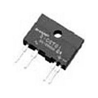
S202SE1 Sharp Electronics, S202SE1 Datasheet
S202SE1
Specifications of S202SE1
Available stocks


Related parts for S202SE1


S202SE1 Summary of contents
Page 1
... S202SE2 Series ∗ Non-zero cross type is also available. (S202SE1 Series) ■ Description S202SE2 Series reinforced insulation type Solid State Relays (SSR) are an integration of an infrared emitting diode (IRED), a Phototriac Detector and a main output Triac. These devices are ideally suited for controlling high voltage AC loads with solid state reliability while providing 3 ...
Page 2
Internal Connection Diagram Zero Crossing Circuit ■ Outline Dimensions ±0.2 18.5 ±0.3 16.4 ±0.2 φ3.2 Common to pin No.1 Common to pin No.1 CSA mark Epoxy resin TÜV mark S202SE2 UL mark Model No. Date ...
Page 3
Date code (2 digit) 1st digit Year of production A.D. Mark A.D Mark 1990 A 2002 P 1991 B 2003 R 1992 C 2004 S 1993 D 2005 T 1994 E 2006 U 1995 F 2007 V 1996 H 2008 ...
Page 4
Absolute Maximum Ratings Parameter Forward current Input Reverse voltage RMS ON-state current Peak one cycle surge current Repetitive peak OFF-state voltage Output Non-Repetitive peak OFF-state voltage Critical rate of rise of ON-state current Operating frequency *1 Isolation voltage Operating ...
Page 5
Model Line-up (1) (Lead-free terminal components) Shipping Package EN60950 (reinforced insulation) − Model No. − ■ Model Line-up (2) (Lead solder plating components) Shipping Package EN60950 (reinforced insulation) − Model No. − Please contact a local SHARP sales representative ...
Page 6
Fig.1 Forward Current vs. Ambient Temperature − Ambient temperature T Fig.3 RMS ON-state Current vs. Case Temperature − Case temperature T ...
Page 7
Fig.7 Minimum Trigger Current vs. Ambient Temperature − Ambient temperature T Remarks : Please be aware that all data in the graph are just for reference. Fig.8 Repetitive Peak OFF-state ...
Page 8
Design Considerations ● Recommended Operating Conditions Parameter Input signal current at ON state Input Input signal current at OFF state Load supply voltage Output Load supply current Frequency Operating temperature ∗ See Fig.2 about derating curve (I ...
Page 9
Make sure there are no warps or bumps on the heat sink, insulation sheet and device surface. (b) Make sure there are no metal dusts or burrs attached onto the heat sink, insulation sheet and device surface. (c) Make ...
Page 10
Degradation In general, the emission of the IRED used in SSR will degrade over time. In the case where long term operation and / or constant extreme temperature fluctuations will be applied to the devices, please allow for a ...
Page 11
Manufacturing Guidelines ● Soldering Method Flow Soldering (No solder bathing) Flow soldering should be completed below 260˚C and within 10s. Preheating is within the bounds of 100 to 150˚C and 30 to 80s. Please solder within one time. Other ...
Page 12
Cleaning instructions Solvent cleaning : Solvent temperature should be 45˚C or below. Immersion time should be 3minutes or less. Ultrasonic cleaning : The impact on the device varies depending on the size of the cleaning bath, ultrasonic output, cleaning ...
Page 13
Package specification Package materials Packing case : Corrugated cardboard Partition : Corrugated cardboard Pad : Corrugated cardboard Cushioning material : Polyethylene Molt plane : Urethane Package method The product should be located after the packing case is partitioned and ...
Page 14
Important Notices · The circuit application examples in this publication are provided to explain representative applications of SHARP devices and are not intended to guarantee any circuit design or license any intellectual property rights. SHARP takes no responsibility for ...