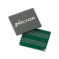
MT46H16M32LFCM-6 IT:B Micron Technology Inc, MT46H16M32LFCM-6 IT:B Datasheet - Page 20

MT46H16M32LFCM-6 IT:B
Manufacturer Part Number
MT46H16M32LFCM-6 IT:B
Description
Manufacturer
Micron Technology Inc
Type
DDR SDRAMr
Datasheet
1.MT46H16M32LFCM-6_ITB.pdf
(98 pages)
Specifications of MT46H16M32LFCM-6 IT:B
Organization
16Mx32
Density
512Mb
Address Bus
15b
Access Time (max)
6.5/5ns
Maximum Clock Rate
166MHz
Operating Supply Voltage (typ)
1.8V
Package Type
VFBGA
Operating Temp Range
-40C to 85C
Operating Supply Voltage (max)
1.95V
Operating Supply Voltage (min)
1.7V
Supply Current
115mA
Pin Count
90
Mounting
Surface Mount
Operating Temperature Classification
Industrial
Lead Free Status / Rohs Status
Compliant
Table 7: Capacitance (x16, x32)
Note 1 applies to all the parameters in this table
PDF: 09005aef82d5d305
512mb_ddr_mobile_sdram_t47m.pdf – Rev. I 12/09 EN
Parameter
Input capacitance: CK, CK#
Delta input capacitance: CK, CK#
Input capacitance: command and address
Delta input capacitance: command and address
Input/output capacitance: DQ, DQS, DM
Delta input/output capacitance: DQ, DQS, DM
Notes:
10. CK and CK# input slew rate must be ≥1 V/ns (2 V/ns if measured differentially).
11. V
12. The value of V
13. DQ and DM input slew rates must not deviate from DQS by more than 10%. 50ps must
3. Tests for AC timing, I
4. Outputs measured with equivalent load; transmission line delay is assumed to be very
5. Timing and I
6. Any positive glitch must be less than one-third of the clock cycle and not more than
7. V
8. To maintain a valid level, the transitioning edge of the input must:
9. V
1. This parameter is sampled. V
2. The input capacitance per pin group will not differ by more than this maximum amount
nominal supply voltage levels, but the related specifications and device operation are
guaranteed for the full voltage range specified.
small:
but input timing is still referenced to V
output timing reference voltage level is V
+200mV or 2.0V, whichever is less. Any negative glitch must be less than one-third of
the clock cycle and not exceed either –150mV or +1.6V, whichever is more positive.
8a. Sustain a constant slew rate from the current AC level through to the target AC lev-
el, V
8b. Reach at least the target AC level.
8c. After the AC target level is reached, continue to maintain at least the target DC lev-
el, V
be greater than one-third of the cycle rate. V
width ≤3ns and the pulse width cannot be greater than one-third of the cycle rate.
el on CK#.
variations in the DC level of the same.
be added to
4 V/ns, functionality is uncertain.
V
fact that they are matched in loading.
for any given device.
DD
IH
ID
DDQ
overshoot: V
is the magnitude of the difference between the input level on CK and the input lev-
and V
IL(AC)
IL(DC)
/2, V
I/O
Or V
or V
OUT
DDQ
Full drive strength
DD
t
DS and
(peak-to-peak) = 0.2V. DM input is grouped with I/O pins, reflecting the
IH(DC)
IH(AC)
must track each other and V
IX
tests may use a V
IH(MAX)
50
is expected to equal V
.
.
Symbol
DD
t
DH for each 100 mV/ns reduction in slew rate. If slew rate exceeds
C
C
C
, and electrical AC and DC characteristics may be conducted at
C
C
= V
DCK
C
DIO
CK
IO
DI
I
20
DDQ
20pF
DD
+ 1.0V for a pulse width ≤3ns and the pulse width cannot
/V
512Mb: x16, x32 Mobile LPDDR SDRAM
IL
DDQ
-to-V
I/O
Micron Technology, Inc. reserves the right to change products or specifications without notice.
= 1.70–1.95V, f = 100 MHz, T
Min
DDQ
IH
DDQ
2.0
2.0
2.0
Half drive strength
–
–
–
swing of up to 1.5V in the test environment,
DDQ
/2 of the transmitting device and must track
/2 (or to the crossing point for CK/CK#). The
DDQ
IL
/2.
50
must be less than or equal to V
undershoot: V
Electrical Specifications
Max
4.0
0.5
4.0
1.0
4.5
1.0
10pF
© 2004 Micron Technology, Inc. All rights reserved.
IL(MIN)
A
= –1.0V for a pulse
= 25˚C, V
Unit
pF
pF
pF
pF
pF
pF
OUT(DC)
DD
Notes
.
2
2
3
=


