AD667KN Analog Devices Inc, AD667KN Datasheet - Page 8
AD667KN
Manufacturer Part Number
AD667KN
Description
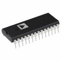
IC DAC 12BIT W/BUFF LATCH 28-DIP
Manufacturer
Analog Devices Inc
Datasheet
1.AD667JNZ.pdf
(8 pages)
Specifications of AD667KN
Mounting Type
Through Hole
Rohs Status
RoHS non-compliant
Settling Time
3µs
Number Of Bits
12
Number Of Converters
1
Voltage Supply Source
Dual ±
Power Dissipation (max)
1W
Operating Temperature
0°C ~ 70°C
Package / Case
28-DIP (0.600", 15.24mm)
Resolution (bits)
12bit
No. Of Pins
28
Peak Reflow Compatible (260 C)
No
Update Rate
0.5MSPS
No. Of Bits
12 Bit
Leaded Process Compatible
No
Interface Type
Serial
Data Interface
-
Lead Free Status / RoHS Status
Contains lead / RoHS non-compliant
Available stocks
Company
Part Number
Manufacturer
Quantity
Price

Company:
Part Number:
AD667KN
Manufacturer:
MAXIM
Quantity:
5 510
Part Number:
AD667KN
Manufacturer:
ADI/亚德诺
Quantity:
20 000


AD667
Right-justified data can be similarly accommodated. The over-
lapping of data lines is reversed, and the address connections
are slightly different. The AD667 still occupies two adjacent
locations in the processor’s memory map. In the circuit of Fig-
ure 9, location X01 loads the 8 LSBs and location X10 loads
the 4 MSBs and updates the output.
USING THE AD667 WITH 12- AND 16-BIT BUSES
The AD667 is easily interfaced to 12- and 16-bit data buses. In
this operation, all four address lines (A0 through A3) are tied
Figure 9. Right-Justified 8-Bit Bus Interface
28-Pin Plastic DIP (N)
28-Contact LCC (E)
Dimensions shown in inches and (mm).
OUTLINE DIMENSIONS
–8–
low, and the latch is enabled by CS going low. The AD667 thus
occupies a single memory location.
This configuration uses the first and second rank registers
simultaneously. The CS input can be driven from an active-low
decoded address. It should be noted that any data bus activity
during the period when CS is low will cause activity at the
AD667 output. If data is not guaranteed stable during this
period, the second rank register can be used to provide double
buffering.
Figure 10. Connections for 12- and 16-Bit Bus Interface
28-Pin Ceramic DIP (D)
28-Terminal Plastic Leaded
Chip Carrier (P)
REV. A
Related parts for AD667KN
Image
Part Number
Description
Manufacturer
Datasheet
Request
R

Part Number:
Description:
±1.7g Dual-Axis IMEMS Accelerometer Evaluation Board
Manufacturer:
Analog Devices Inc
Datasheet:

Part Number:
Description:
Inertial Sensor Evaluation System
Manufacturer:
Analog Devices Inc
Datasheet:
Part Number:
Description:
Manufacturer:
Analog Devices Inc
Datasheet:
Part Number:
Description:
Manufacturer:
Analog Devices Inc
Datasheet:
Part Number:
Description:
Manufacturer:
Analog Devices Inc
Datasheet:
Part Number:
Description:
Manufacturer:
Analog Devices Inc
Datasheet:
Part Number:
Description:
Manufacturer:
Analog Devices Inc
Datasheet:
Part Number:
Description:
Manufacturer:
Analog Devices Inc
Datasheet:
Part Number:
Description:
Manufacturer:
Analog Devices Inc
Datasheet:
Part Number:
Description:
Manufacturer:
Analog Devices Inc
Datasheet:
Part Number:
Description:
Manufacturer:
Analog Devices Inc
Datasheet:
Part Number:
Description:
Manufacturer:
Analog Devices Inc
Datasheet:
Part Number:
Description:
Manufacturer:
Analog Devices Inc
Datasheet: