MAL215947151E3 Vishay, MAL215947151E3 Datasheet - Page 2
MAL215947151E3
Manufacturer Part Number
MAL215947151E3
Description
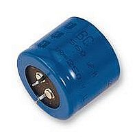
CAPACITOR, 150UF 450V CAPACITOR, 150UF 450V
Manufacturer
Vishay
Series
2222159r
Datasheet
1.MAL215952331E3.pdf
(8 pages)
Specifications of MAL215947151E3
Capacitance
150UF
Voltage Rating, Dc
450V
Capacitor Dielectric Type
ALUMINIUM ELECTROLYTIC
Temp, Op. Max
105(DEGREE C)
Temp, Op. Min
-25(DEGREE C)
Tolerance,
20%
Rohs Compliant
YES
Available stocks
Company
Part Number
Manufacturer
Quantity
Price
Company:

Part Number:
MAL215947151E3
Manufacturer:
Vishay
Quantity:
300


TWO TERMINAL SNAP-IN
www.vishay.com
100
159 PUL-SI
Vishay BCcomponents
DIMENSIONS in millimeters AND AVAILABLE FORMS
THREE TERMINAL SNAP-IN
SELECTION CHART FOR C
1000
1200
1500
1800
(µF)
C
220
270
330
390
470
560
680
820
+ Terminal
- Terminal
Minus pole
R
+ Terminal
- Terminal
marking
The negative terminal has TWO pins which are BOTH
The minus terminal can be marked with a black dot
Bottom view
Fig.4 Two terminal snap-in
Bottom view
Fig.2 Two terminal snap-in
or with an imprinted ‘-’ sign.
electrcally connected
22 x 30
22 x 35
25 x 30
22 x 40
30 x 25
25 x 35
30 x 30
25 x 45
30 x 30
35 x 25
25 x 50
30 x 35
35 x 30
30 x 45
35 x 35
30 x 50
35 x 35
35 x 45
35 x 50
200
L
-
-
-
-
-
-
-
-
-
L
For technical questions, contact: aluminumcaps2@vishay.com
R
, U
Ø D
R
Ø D
Power Ultra Long Life Snap-In
AND RELEVANT NOMINAL CASE SIZES (Ø D x L in mm)
Aluminum Capacitors
L + 2 max.
4 ± 0.5
5.8
L + 2 max.
22 x 30
25 x 25
22 x 35
25 x 30
30 x 25
22 x 40
25 x 30
30 x 25
25 x 35
30 x 30
25 x 40
30 x 30
35 x 25
25 x 45
30 x 35
35 x 30
30 x 40
35 x 35
30 x 45
35 x 35
35 x 40
35 x 40
35 x 45
35 x 45
35 x 50
+ 0
250
- 1
mm
-
-
-
-
± 0.1
3.3
U
R
(V)
Ø
2.5 ± 0.1
4.75 ± 0.1
Ø
2 ± 0.1 (2 x)
Fig.5 Mounting hole diagram
25 x 45
30 x 35
35 x 30
25 x 50
30 x 40
35 x 30
30 x 45
35 x 35
30 x 50
35 x 40
35 x 45
35 x 60
400
Fig.3 Mounting hole diagram
-
-
-
-
-
-
-
-
-
-
-
-
-
-
-
-
Ø 2 ± 0.1 (2 x)
± 0.1
10
The 10 mm spacing of the 2 pin
snap-in is used as the base layout
and a third hole is added.
The third hole is closer to the
negative primary hole so that
polarization is always maintained,
together with added mechanical
stability.
Document Number: 28341
±0.1
10
Revision: 14-Oct-08
30 x 40
35 x 30
30 x 45
35 x 35
30 x 50
35 x 40
35 x 45
35 x 50
35 x 60
450
-
-
-
-
-
-
-
-
-
-
-
-
-
-
-
-
-
-
-
Related parts for MAL215947151E3
Image
Part Number
Description
Manufacturer
Datasheet
Request
R

Part Number:
Description:
357-036-542-201 CARDEDGE 36POS DL .156 BLK LOPRO
Manufacturer:
Vishay
Datasheet:
Part Number:
Description:
357-036-542-201 CARDEDGE 36POS DL .156 BLK LOPRO
Manufacturer:
Vishay
Datasheet:
Part Number:
Description:
357-036-542-201 CARDEDGE 36POS DL .156 BLK LOPRO
Manufacturer:
Vishay
Datasheet:
Part Number:
Description:
357-036-542-201 CARDEDGE 36POS DL .156 BLK LOPRO
Manufacturer:
Vishay
Datasheet:
Part Number:
Description:
357-036-542-201 CARDEDGE 36POS DL .156 BLK LOPRO
Manufacturer:
Vishay
Datasheet:
Part Number:
Description:
357-036-542-201 CARDEDGE 36POS DL .156 BLK LOPRO
Manufacturer:
Vishay
Datasheet:
Part Number:
Description:
357-036-542-201 CARDEDGE 36POS DL .156 BLK LOPRO
Manufacturer:
Vishay
Datasheet:
Part Number:
Description:
357-036-542-201 CARDEDGE 36POS DL .156 BLK LOPRO
Manufacturer:
Vishay
Datasheet:
Part Number:
Description:
357-036-542-201 CARDEDGE 36POS DL .156 BLK LOPRO
Manufacturer:
Vishay
Datasheet:
Part Number:
Description:
357-036-542-201 CARDEDGE 36POS DL .156 BLK LOPRO
Manufacturer:
Vishay
Datasheet:
Part Number:
Description:
357-036-542-201 CARDEDGE 36POS DL .156 BLK LOPRO
Manufacturer:
Vishay
Datasheet:
Part Number:
Description:
357-036-542-201 CARDEDGE 36POS DL .156 BLK LOPRO
Manufacturer:
Vishay
Datasheet:
Part Number:
Description:
357-036-542-201 CARDEDGE 36POS DL .156 BLK LOPRO
Manufacturer:
Vishay
Datasheet:
Part Number:
Description:
357-036-542-201 CARDEDGE 36POS DL .156 BLK LOPRO
Manufacturer:
Vishay
Datasheet:
Part Number:
Description:
357-036-542-201 CARDEDGE 36POS DL .156 BLK LOPRO
Manufacturer:
Vishay
Datasheet: