C333C103K2G5TA Kemet, C333C103K2G5TA Datasheet - Page 8
C333C103K2G5TA
Manufacturer Part Number
C333C103K2G5TA
Description
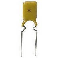
CAPACITOR CERAMIC, 0.01UF, 200V, C0G/NP0, Radial
Manufacturer
Kemet
Series
Gold Maxr
Datasheet
1.C315C271F1G5TA.pdf
(16 pages)
Specifications of C333C103K2G5TA
Dielectric Characteristic
C0G / NP0
Capacitance
0.01µF
Capacitance Tolerance
± 10%
Voltage Rating
200VDC
Capacitor Case Style
Radial Leaded
No. Of Pins
2
Rohs Compliant
Yes


Drawings are not to scale. See table below for dimensions. See page 16 for optional lead configurations.
(1) Lead configuration depends on capacitance value. (2) H dimensions does not include meniscus.
Note: 1 inch = 25.4mm.
Note (1): Measured at seating plane.
Note (2): Thickness = 0.16" (4.064mm) for C320 from 4.7 - 10.0 F.
Case
C315
C317
C320
C322
C323
C330
C333
C340
C350
Size
CAPACITANCE PICOFARAD CODE
Expressed in picofarads (pF). First two
digits represent significant figures. Third
digit specifies number of zeros. Use 9 for
1.0 thru 9.9 pF. Example 2.2pF = 229
CAPACITANCE TOLERANCE
C0G: C – ±0.25pF; D – ±0.5pF; F – ±1%;
X7R: K – ±10%; M – ±20%; P – 0, -100%;
Z5U: M – ±20%; P – 0, -100%; Z – -20,+80%
SPECIFICATION
C – Standard
CASE SIZE
See Table Above
CERAMIC
© KEMET Electronics Corporation, P.O. Box 5928, Greenville, S.C. 29606, (864) 963-6300
Z – -20,+80%
G – ±2%; J – ±5%,
0.400 (10.16)
0.500 (12.70)
0.150 (3.81)
0.150 (3.81)
0.200 (5.08)
0.200 (5.08)
0.200 (5.08)
0.300 (7.62)
0.300 (7.62)
Max.
STANDARD LEAD CONFIGURATION
L
C 320 C
CERAMIC CONFORMALLY COATED/RADIAL
(1)
For packaging information, see pages 47 and 48.
0.460 (11.68)
0.560 (14.22)
0.210 (5.33)
0.230 (5.84)
0.260 (6.60)
0.260 (6.60)
0.320 (8.13)
0.360 (9.14)
0.390 (9.91)
“STANDARD & HIGH VOLTAGE GOLD MAX”
DIMENSIONS INCHES (MILLIMETERS)
Max.
H.
ORDERING INFORMATION
102
0.125 (3.18)
0.100 (2.54)
0.100 (2.54)
0.125 (3.18)
0.125 (3.18)
0.150 (3.81)
0.150 (3.81)
0.150 (3.81)
0.200 (5.08)
Standard
T Max.
M
(2)
1
High Voltage
0.150 (3.81)
0.150 (3.81)
0.200 (5.08)
0.200 (5.08)
0.200 (5.08)
0.250 (6.35)
0.250 (6.35)
0.270 (6.86)
0.270 (6.86)
T Max.
R
OUTLINE DRAWINGS
5
0.400 (10.16)
0.100 (2.54)
0.200 (5.08)
0.100 (2.54)
0.200 (5.08)
0.200 (5.08)
0.200 (5.08)
0.200 (5.08)
0.200 (5.08)
±.030 (.78)
S
T
(1)
G – C0G (NP0) - Ultra Stable
R – X7R - Stable
U – Z5U - General Purpose
(1)
INTERNAL CONSTRUCTION
T – 100% Tin (Sn)
H – 60/40% Tin/Lead (SnPb)
A
3 – 25
5 – 50
1 – 100
2 – 200
A – 250
C – 500
RATED VOLTAGE (DC)
-.001(.025)
0.020 (.51)
0.020 (.51)
0.020 (.51)
0.020 (.51)
0.020 (.51)
0.020 (.51)
0.020 (.51)
0.020 (.51)
0.025 (.64)
+.004(.10)
A – Not Applicable
LEAD MATERIAL
LD
FAILURE RATE
EIA Designation
DIELECTRIC
5 – Multilayer
D – 1000
F – 1500
G – 2000
Z – 2500
H – 3000
0.276 (7.00)
0.276 (7.00)
0.276 (7.00)
0.276 (7.00)
0.276 (7.00)
0.276 (7.00)
0.276 (7.00)
0.276 (7.00)
0.276 (7.00)
Min.
LL
15
Related parts for C333C103K2G5TA
Image
Part Number
Description
Manufacturer
Datasheet
Request
R

Part Number:
Description:
CAP, KEMET #F601BL105K250C
Manufacturer:
Kemet
Datasheet:
Part Number:
Description:
Manufacturer:
Kemet
Datasheet:
Part Number:
Description:
Manufacturer:
Kemet
Datasheet: