12063E104MAT2A AVX Corporation, 12063E104MAT2A Datasheet - Page 31
12063E104MAT2A
Manufacturer Part Number
12063E104MAT2A
Description
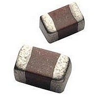
CAPACITOR CERAMIC, 0.1UF, 25V, Z5U, 1206
Manufacturer
AVX Corporation
Datasheet
1.12065E104MAT2A.pdf
(49 pages)
Specifications of 12063E104MAT2A
Dielectric Characteristic
Z5U
Capacitance
0.1µF
Capacitance Tolerance
± 20%
Voltage Rating
25VDC
Capacitor Case Style
1206
No. Of Pins
2
Capacitor Mounting
SMD
Rohs Compliant
Yes


30
MIL-PRF-55681/Chips
Military Part Number Identification
CDR31 thru CDR35
CROSS REFERENCE: AVX/MIL-PRF-55681/CDR31 THRU CDR35
MIL Style: CDR31, CDR32, CDR33, CDR34, CDR35
Voltage Temperature Limits:
BP = 0 ± 30 ppm/°C without voltage; 0 ± 30 ppm/°C with
BX = ± 15% without voltage; +15 –25% with rated voltage
Capacitance: Two digit figures followed by multiplier
(number of zeros to be added) e.g., 101 = 100 pF
Rated Voltage: A = 50V, B = 100V
Capacitance Tolerance: C ±.25 pF, D ±.5 pF, F ±1%
Per MIL-PRF-55681
T
(Metric Sizes)
from -55°C to +125°C
rated voltage from -55°C to +125°C
CDR31
CDR32
CDR33
CDR34
CDR35
W
Style
0805
1206
1210
1812
1825
AVX
J ±5%, K ±10%, M ±20%
Length (L)
D
L
(mm)
2.00
3.20
3.20
4.50
4.50
t
Width (W)
(mm)
1.25
1.60
2.50
3.20
6.40
MILITARY DESIGNATION PER MIL-PRF-55681
Part Number Example
(example)
MIL Style
Voltage-temperature
Limits
Capacitance
Rated Voltage
Capacitance Tolerance
Termination Finish
Failure Rate
Thickness (T)
Termination Finish:
M = Palladium Silver
N = Silver Nickel Gold
S = Solder-coated
*Solder shall have a melting point of 200°C or less.
Failure Rate Level: M = 1.0%, P = .1%, R = .01%,
Packaging: Bulk is standard packaging. Tape and reel
per RS481 is available upon request.
Max. (mm)
1.3
1.3
1.5
1.5
1.5
CDR31
Min. (mm)
BP
.50
—
—
—
—
S = .001%
D
101
U = Base Metallization/Barrier
W = Base Metallization/Barrier
Metal/Solder Coated*
Metal/Tinned (Tin or Tin/
Lead Alloy)
Max. (mm)
B
Termination Band (t)
.70
.70
.70
.70
.70
K
S
Min. (mm)
M
.30
.30
.30
.30
.30
Related parts for 12063E104MAT2A
Image
Part Number
Description
Manufacturer
Datasheet
Request
R

Part Number:
Description:
Manufacturer:
AVX Corporation
Datasheet:
Part Number:
Description:
Manufacturer:
AVX Corporation
Datasheet:
Part Number:
Description:
Manufacturer:
AVX Corporation
Datasheet:
Part Number:
Description:
Manufacturer:
AVX Corporation
Datasheet:
Part Number:
Description:
Manufacturer:
AVX Corporation
Datasheet: