AD558KNZ Analog Devices Inc, AD558KNZ Datasheet - Page 3
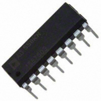
AD558KNZ
Manufacturer Part Number
AD558KNZ
Description
IC DAC 8BIT 5-15V IN MONO 16DIP
Manufacturer
Analog Devices Inc
Series
DACPORT®r
Datasheet
1.AD558JNZ.pdf
(8 pages)
Specifications of AD558KNZ
Data Interface
Parallel
Settling Time
800ns
Number Of Bits
8
Number Of Converters
1
Voltage Supply Source
Single Supply
Power Dissipation (max)
375mW
Operating Temperature
0°C ~ 70°C
Mounting Type
Through Hole
Package / Case
16-DIP (0.300", 7.62mm)
Resolution (bits)
8bit
Sampling Rate
1.25MSPS
Input Channel Type
Parallel
Supply Current
15mA
Digital Ic Case Style
DIP
No. Of Pins
16
Number Of Channels
1
Resolution
8b
Conversion Rate
1.25MSPS
Interface Type
Parallel
Single Supply Voltage (typ)
5/9/12/15V
Dual Supply Voltage (typ)
Not RequiredV
Architecture
R-2R
Power Supply Requirement
Single
Output Type
Voltage
Integral Nonlinearity Error
±0.25+/- LSB
Single Supply Voltage (min)
4.5V
Single Supply Voltage (max)
16.5V
Dual Supply Voltage (min)
Not RequiredV
Dual Supply Voltage (max)
Not RequiredV
Operating Temp Range
0C to 70C
Operating Temperature Classification
Commercial
Mounting
Through Hole
Pin Count
16
Package Type
PDIP
Lead Free Status / RoHS Status
Lead free / RoHS Compliant
Lead Free Status / RoHS Status
Lead free / RoHS Compliant, Lead free / RoHS Compliant
Available stocks
Company
Part Number
Manufacturer
Quantity
Price
Company:

Part Number:
AD558KNZ
Manufacturer:
SHARP
Quantity:
6 222


REV. A
ABSOLUTE MAXIMUM RATINGS*
V
Digital Inputs (Pins 1–10) . . . . . . . . . . . . . . . . . . 0 V to +7.0 V
V
Power Dissipation . . . . . . . . . . . . . . . . . . . . . . . . . . . . 450 mW
Storage Temperature Range
Lead Temperature (soldering, 10 sec) . . . . . . . . . . . . . +300 C
Thermal Resistance
*Stresses greater than those listed under “Absolute Maximum Ratings” may cause
permanent damage to the device. This is a stress rating only and functional
operation of the device at these or any other conditions above those indicated in the
operational section of this specification is not implied. Exposure to absolute
maximum rating conditions for extended periods may affect device reliability.
CC
OUT
N/P (Plastic) Packages . . . . . . . . . . . . . . . . –25 C to +100 C
D (Ceramic) Package . . . . . . . . . . . . . . . . . –55 C to +150 C
Junction to Ambient/Junction to Case
to Ground . . . . . . . . . . . . . . . . . . . . . . . . . . . 0 V to +18 V
D (Ceramic) Package . . . . . . . . . . . . . . 100 C/W/30 C/W
N/P (Plastic) Packages . . . . . . . . . . . . . 140 C/W/55 C/W
. . . . . . . . . . . . . . . . . . . . . . . Indefinite Short to Ground
Figure 1a. AD558 Pin Configuration (DIP)
AD558 METALIZATION PHOTOGRAPH
Dimensions shown in inches and (mm).
Model
AD558JN
AD558JP
AD558JD
AD558KN
AD558KP
AD558KD
AD558SD
AD558TD
NOTES
1
2
For details on grade and package offerings screened in accordance with MIL-STD-883, refer to the Analog Devices
D = Ceramic DIP; N = Plastic DIP; P = Plastic Leaded Chip Carrier.
Military Products Databook or current AD558/883B data sheet.
1
Temperature
0 C to +70 C
0 C to +70 C
0 C to +70 C
0 C to +70 C
0 C to +70 C
0 C to +70 C
–55 C to +125 C
–55 C to +125 C
Momentary Short to V
ORDERING GUIDE
Relative Accuracy
Error Max
T
1/2 LSB
1/2 LSB
1/2 LSB
1/4 LSB
3/8 LSB
MIN
1/4 LSB
1/4 LSB
3/4 LSB
CC
–3–
to T
MAX
Figure 1b. AD558 Pin Configuration (PLCC and LCC)
Figure 1a. AD558 Pin Configuration (DIP)
Full-Scale
Error, Max
T
DB2
DB3
DB4
DB5
(LSB) DB0
(MSB) DB7
NC
2.5 LSB
2.5 LSB
2.5 LSB
1 LSB
1 LSB
1 LSB
2.5 LSB
1 LSB
MIN
4
5
7
8
6
DB1
DB2
DB3
DB4
DB5
DB6
to T
(Not to Scale)
9 10 11 12 13
1
2
3
4
5
6
8
3
MAX
7
TOP VIEW
AD558
(Not to Scale)
2
TOP VIEW
AD558
1
20 19
Package
Option
Plastic (N-16)
PLCC (P-20A)
TO-116 (D-16)
Plastic (N-16)
PLCC (P-20A)
TO-116 (D-16)
TO-116 (D-16)
TO-116 (D-16)
NC = NO CONNECT
16
15
14
13
12
11
10
18
17
16
15
14
9
2
V
V
V
GND
GND
+V
CS
CE
V
GND
NC
GND
+V
OUT
OUT
OUT
OUT
CC
CC
SENSE
SELECT
SELECT
AD558
Related parts for AD558KNZ
Image
Part Number
Description
Manufacturer
Datasheet
Request
R

Part Number:
Description:
±1.7g Dual-Axis IMEMS Accelerometer Evaluation Board
Manufacturer:
Analog Devices Inc
Datasheet:

Part Number:
Description:
Inertial Sensor Evaluation System
Manufacturer:
Analog Devices Inc
Datasheet:
Part Number:
Description:
Manufacturer:
Analog Devices Inc
Datasheet:
Part Number:
Description:
Manufacturer:
Analog Devices Inc
Datasheet:
Part Number:
Description:
Manufacturer:
Analog Devices Inc
Datasheet:
Part Number:
Description:
Manufacturer:
Analog Devices Inc
Datasheet:
Part Number:
Description:
Manufacturer:
Analog Devices Inc
Datasheet:
Part Number:
Description:
Manufacturer:
Analog Devices Inc
Datasheet:
Part Number:
Description:
Manufacturer:
Analog Devices Inc
Datasheet:
Part Number:
Description:
Manufacturer:
Analog Devices Inc
Datasheet:
Part Number:
Description:
Manufacturer:
Analog Devices Inc
Datasheet:
Part Number:
Description:
Manufacturer:
Analog Devices Inc
Datasheet:
Part Number:
Description:
Manufacturer:
Analog Devices Inc
Datasheet: