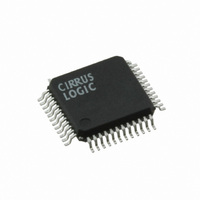
CS4385-DQZ Cirrus Logic Inc, CS4385-DQZ Datasheet - Page 38

CS4385-DQZ
Manufacturer Part Number
CS4385-DQZ
Description
IC DAC 8CH 114DB 192KHZ 48LQFP
Manufacturer
Cirrus Logic Inc
Datasheet
1.CS4385-CQZ.pdf
(55 pages)
Specifications of CS4385-DQZ
Data Interface
Serial
Number Of Bits
24
Number Of Converters
8
Voltage Supply Source
Analog and Digital
Power Dissipation (max)
520mW
Operating Temperature
-40°C ~ 105°C
Mounting Type
Surface Mount
Package / Case
48-LQFP
Resolution (bits)
24bit
Sampling Rate
192kSPS
Input Channel Type
Serial
Supply Voltage Range - Analog
4.75V To 5.25V
Supply Current
84mA
Digital Ic Case Style
QFP
Lead Free Status / RoHS Status
Lead free / RoHS Compliant
For Use With
598-1154 - BOARD EVAL FOR CS4385 DAC
Settling Time
-
Lead Free Status / RoHS Status
Lead free / RoHS Compliant, Lead free / RoHS Compliant
Other names
598-1649
Available stocks
Company
Part Number
Manufacturer
Quantity
Price
Company:
Part Number:
CS4385-DQZ
Manufacturer:
Cirrus Logic Inc
Quantity:
135
Company:
Part Number:
CS4385-DQZ
Manufacturer:
Maxim
Quantity:
84
Company:
Part Number:
CS4385-DQZR
Manufacturer:
Cirrus Logic Inc
Quantity:
10 000
38
6.2.3 PCM/DSD Selection (DSD/PCM)
6.2.4 DAC Pair Disable (DACx_DIS)
6.2.5 Power Down (PDN)
6.3
6.3.1 Digital Interface Format (DIF)
DIF3
0
7
PCM Control (address 03h)
Default = 0
0 - PCM
1 - DSD
Function:
This function selects DSD or PCM Mode. The appropriate data and clocks should be present before
changing modes, or else MUTE should be selected.
Default = 0
0 - DAC Pair x Enabled
1 - DAC Pair x Disabled
Function:
When the bit is set, the respective DAC channel pair (AOUTAx and AOUTBx) will remain in a reset state.
It is advised that changes to these bits be made while the power-down (PDN) bit is enabled to eliminate
the possibility of audible artifacts.
Note:
terface Format
Default = 1
0 - Disabled
1 - Enabled
Function:
The entire device will enter a low-power state when this function is enabled, and the contents of the control
registers are retained in this mode. The power-down bit defaults to ‘enabled’ on power-up and must be
disabled before normal operation in Control Port Mode can occur.
Default = 0000 - Format 0 (Left-Justified, up to 24-bit data)
Function:
These bits select the interface format for the serial audio input. The DSD/PCM bit determines whether
PCM or DSD Mode is selected.
The required relationship between the Left/Right clock, serial clock and serial data is defined by the Digital
Interface Format and the options are detailed in
Note:
to ensure proper switching from one mode to another.
When the device is configured in TDM Mode by setting the DIF[3:0] bits to 1100 (see
While in PCM Mode, the DIF bits should only be changed when the power-down (PDN) bit is set
DIF2
6
0
(DIF)), this function is not available and these bits must be set to 0 for proper operation.
DIF1
5
0
DIF0
0
4
Figures 9
Reserved
3
0
through 19.
Reserved
2
0
FM1
1
1
CS4385
Digital In-
DS671F2
FM0
0
1


