5499910-6 TE Connectivity, 5499910-6 Datasheet - Page 2
5499910-6
Manufacturer Part Number
5499910-6
Description
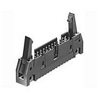
WIRE-BOARD CONN, HEADER, 26POS, 2.54MM
Manufacturer
TE Connectivity
Series
Amp Latch Seriesr
Specifications of 5499910-6
Peak Reflow Compatible (260 C)
No
Tail Length
2.79mm
Leaded Process Compatible
Yes
Connector Type
Wire-to-Board
Rohs Compliant
Yes
No. Of Contacts
26
Contact Plating
Gold
Product Type
Headers - Latch / Eject
Pitch
2 mm
Number Of Positions / Contacts
44
Number Of Rows
2
Mounting Style
Through Hole
Termination Style
Solder
Product Line
AMP-LATCH
Profile
Standard
Pcb Mounting Orientation
Vertical
Pcb Mount Retention
Without
Mating Connector Lock
With
Housing Style
4-Sided
Ejection Latches
With
Post Size (mm [in])
0.64 [.025]
Shrouded
Yes
Latch Type
Short
Mating Connector Lock Type
Latch
Termination Post Length (mm [in])
2.79 [0.110]
Solder Tail Contact Plating
Tin
Header Type
Universal Ejection Pin Headers
Number Of Positions
26
Centerline, Matrix (mm [in])
2.54 x 2.54 [.100 x .100]
Preloaded
Yes
Contact Plating, Mating Area, Material
Gold (15)
Contact Shape
Square
Connector Style
Header - Pin
Mating Alignment Type
Center, Dual Polarizing Bar, Military
Mating Alignment
With
Housing Material
Thermoplastic - GF
Ul Flammability Rating
UL 94V-0
Housing Color
Black
Rohs/elv Compliance
RoHS compliant, ELV compliant
Lead Free Solder Processes
Wave solder capable to 240°C, Wave solder capable to 260°C, Wave solder capable to 265°C
Rohs/elv Compliance History
Always was RoHS compliant
Temperature Rating
Standard
Pcb Thickness, Recommended (mm [in])
1.57 [0.062]
Lead Free Status / Rohs Status
Details


3.3.
3.4.
3.5.
Exam ination of product.
Insulation resistance.
W ithstanding voltage.
Solderability.
Com ponent resistance to wave
soldering.
Contact retention.
Rev F
Ratings
!
!
!
Perform ance and Test Description
Product is designed to m eet electrical, m echanical and environm ental perform ance requirem ents
specified in Figure 1. Unless otherwise specified, all tests shall be perform ed at am bient environm ental
conditions per Test Specification 109-1.
Test Requirem ents and Procedures Sum m ary
Test Description
Voltage: 250 volts AC
Current: Signal application only, 1 am pere m axim um per contact
Tem perature: -65 to 105°C
Meets requirem ents of product
drawing.
5000 m egohm s m inim um initial.
1000 m egohm s m inim um final.
One m inute hold with no breakdown
or flashover.
Solderable area shall have
m inim um of 95% solder coverage.
See Note.
Post shall not dislodge from norm al
position.
Figure 1 (continued)
MECHANICAL
ELECTRICAL
Requirem ent
Visual, dim ensional and functional
per applicable quality inspection
plan.
EIA-364-21.
500 volts DC, 2 m inute hold.
Test between adjacent contacts of
unm ated specim ens.
EIA-364-20, Condition I.
1000 volts AC at sea level.
Test between adjacent contacts of
unm ated specim ens.
TE Spec 109-11-1.
Subject contacts to solderability for
specim ens with tin-lead plated
soldertails.
TE Spec 109-11-11.
Subject contacts to solderability for
specim ens with lead-free tin plated
soldertails.
TE Spec 109-202, Condition A.
240°C for specim ens with tin-lead
plated soldertails.
TE Spec 109-202, Condition B.
265°C for specim ens with lead-free
tin plated soldertails.
EIA-364-29, Method A.
Apply axial load of 2 pounds to
contacts and hold for 6 seconds.
See Figure 3.
Procedure
108-40018
2 of 5
Related parts for 5499910-6
Image
Part Number
Description
Manufacturer
Datasheet
Request
R

Part Number:
Description:
Printers THERMAL PRINTER HS-SLEEVE MARKER
Manufacturer:
TE Connectivity


Part Number:
Description:
Manufacturer:
TE Connectivity
Datasheet:


Part Number:
Description:
Manufacturer:
TE Connectivity
Datasheet:

Part Number:
Description:
Manufacturer:
TE Connectivity
Datasheet:

Part Number:
Description:
Manufacturer:
TE Connectivity
Datasheet:


Part Number:
Description:
Manufacturer:
TE Connectivity
Datasheet:

Part Number:
Description:
Manufacturer:
TE Connectivity
Datasheet: