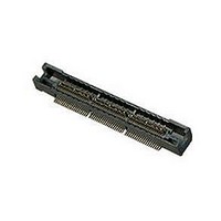
5767054-2 TE Connectivity, 5767054-2 Datasheet

5767054-2
Specifications of 5767054-2
Available stocks
Related parts for 5767054-2
5767054-2 Summary of contents
Page 1
Position A2 Position A1 A Optional Pick-Up Cap Ø 0.76 0.55 Solder Balls Ref. [.030] [.022] Contacts In These Rows Are Tied Together (Commoned) Ø 0.60–0.55 [.024–.022] 0.65 73x [.026] 1.30 36x [.051] C Recommended PC Board Layout Dimensions No. ...
Page 2
ontinued) ...
Page 3
...
Page 4
( ontinued) ...
Page 5
6.60 18.00 15.60 27.00 22.86 11.00 9.00 20.00 18.75 29.00 27.80 12.57 21.60 31.90 ...
Page 6
( ontinued) ...
Page 7
A [± .008] + 0.00 – 0. .000 [ ] – .002 18 Spaces at 0.64 ± 0.20 [.025 ± .008 ] ± 0.20 ± .008 = 11.43 [.450 ] ± 0.20 C [± .008] Standard ...
Page 8
( ontinued) 1.35 2.72 2.64 25.40 22.81 11.43 1.35 2.72 2.64 1.35 2.72 12.70 2.64 38.10 31.70 24.13 1.35 2.72 2.64 1.35 2.72 25.40 2.64 50.80 48.21 36.83 1.35 2.72 2.64 1.35 2.72 38.10 2.64 63.50 60.91 49.53 1.35 2.72 ...
Page 9
A [± .008] + 0.00 – 0. .000 [ ] – .002 18 Spaces at 0.64 ± 0.20 [.025 ± .008 ] ± 0.20 ± .008 = 11.43 [.450 ] ± 0.20 C [± ...
Page 10
Note: 1.52 2.74 1.52 2.74 1.52 2.74 12.70 1.52 2.74 1.52 2.74 25.40 1.52 2.74 1.52 2.74 ...
Page 11
A [± .008] + 0.00 – 0. .000 [ ] – .002 18 Spaces at 0.64 ± 0.20 [.025 ± .008 ] = 11.43 ± 0.20 [.450 ± .008 ] ± 0.20 C [± ...
Page 12
( ontinued) 1.52 2.64 25.40 22.81 11.43 1.52 2.64 1.52 12.70 2.64 38.10 31.70 24.13 1.52 2.64 1.52 25.40 2.64 50.80 48.21 36.83 1.52 2.64 1.52 38.10 2.64 63.50 60.91 49.53 1.52 2.64 1.52 50.80 2.64 76.20 73.61 62.23 1.52 ...
Page 13
A [± .008] + 0.00 – 0. .000 [ ] – .002 18 Spaces at 0.64 ± 0.20 [.025 ± .008 ] = 11.43 ± 0.20 [.450 ± .008 ] ± 0.20 C [± ...
Page 14
( ontinued) 1.52 2.64 25.40 22.81 11.43 1.52 2.64 1.52 12.70 2.64 38.10 31.70 24.13 1.52 2.64 1.52 25.40 2.64 50.80 48.21 36.83 1.52 2.64 1.52 38.10 2.64 63.50 60.91 49.53 1.52 2.64 1.52 50.80 2.64 76.20 73.61 62.23 1.52 ...
Page 15
A [± .008] + 0.00 – 0. .000 [ ] – .002 18 Spaces at 0.64 ± 0.15 [.025 ± .006 ] ± 0.15 ± .006 = 11.43 [.450 ] ± 0.15 C [± ...
Page 16
Note: 0.00 12.70 25.40 38.10 50.80 63.50 76.20 ...
Page 17
Pad Ø 0.81 ± 0.05 [.032 ± .002 Hole R 0.13 [.005] 0.13 [.005] x 45° No. of Pos. Note: ( ontinued) ...
Page 18
Pad ± 0.05 Ø 0.81 ± .002 [.032 Hole R 0.13 [.005] 0.13 [.005] x 45° Notes: ± 0.20 A [± .008] ...
Page 19
No. of Pos 25.40 22.81 38.10 35.51 50.80 48.21 63.50 60.91 76.20 73.61 88.90 86.31 101.60 99.00 Note: Dimensions Plating 11.43 0.00 24.13 12.70 36.83 25.40 49.53 38.10 62.23 50.80 74.93 63.50 87.63 76.20 ...
Page 20
Pad ± 0.05 Ø 0.81 ± .002 [.032 Hole R 0.13 [.005] 0.13 [.005] x 45° Notes: ± 0.20 A [± .008] ...
Page 21
No. of Pos 25.40 22.81 38.10 35.51 50.80 48.21 63.50 60.91 76.20 73.61 88.90 86.31 101.60 99.00 Note: Dimensions Plating 11.43 0.00 24.13 12.70 36.83 25.40 49.53 38.10 62.23 50.80 74.93 63.50 87.63 76.20 ...
Page 22
Pad 3.73 [.147] ± 0.20 A [± .008] + 0.00 – 0. ...
Page 23
Dimensions No. of Pos 25.40 22.81 11.43 38.10 35.51 24.13 50.80 48.21 36.83 63.50 60.91 49.53 76.20 73.61 62.23 88.90 86.31 74.93 101.60 99.00 87.63 Note: Solder Tail 1.52 0.00 2.31 1.52 12.70 2.31 ...
Page 24
F [± .006] 0.43 [.017 1.27 [.050] Pad ± 0.05 Ø 0.81 ± .002 [.032 ] Dia. Typ. For Barbed Parts; Ø 0.64 ± 0.05 [.025 ...
Page 25
Dimensions No. of Pos 1.40 2.74 25.40 22.86 11.43 1.40 2.74 1.40 2.74 38.10 35.56 24.13 12.70 1.40 2.74 1.40 2.74 50.80 48.26 36.83 25.40 1.40 2.74 1.40 2.74 63.50 60.96 49.53 38.10 1.40 ...
Page 26
F [± .006] 0.43 [.017 1.27 [.050] Pad Ø 0.81 ± 0.05 ± .002 [.032 Dia. Typ. For Barbed Parts; Ø 0.64 ± 0.05 [.025 ± ...
Page 27
Dimensions No. of Pos 1.37 1.37 2.72 25.40 22.86 11.43 1.37 1.37 2.72 1.37 1.37 12.70 2.72 38.10 35.56 24.13 1.37 1.37 2.72 1.37 1.37 25.40 2.72 50.80 48.26 36.83 1.37 1.37 2.72 1.37 ...
Page 28
Pad 3.73 [.147 0.08 – 0. .003 [ ] – .000 18 ...


