1-2058703-1 TE Connectivity, 1-2058703-1 Datasheet

CONNECTOR, BLADE & RECEPTACLE, 2WAY

1-2058703-1

Manufacturer Part Number
1-2058703-1
Description
CONNECTOR, BLADE & RECEPTACLE, 2WAY
Manufacturer
TE Connectivity
Datasheet

Specifications of 1-2058703-1

Connector Type
Board To Board
Pitch Spacing
4mm
No. Of Rows
1
No. Of Contacts
2
Gender
Receptacle
Contact Termination
Surface Mount Horizontal
Contact Plating
Tin
Contact Material
Copper
Rohs Compliant
Yes
Colour
Black
Svhc
No SVHC
Product Type
Connector
Sealed
No
Termination Method To Pc Board
Surface Mount
Pcb Mount Retention
With
Pcb Mount Alignment
Without
Smt Compatible
Yes
Mount Angle
Right Angle
Ul File Number
E28476
Keyed
No
Make First / Break Last
No
Mating Retention Type
Latching
Contact Current Rating, Max (a)
5
Operating Voltage (vac)
90
Operating Voltage (vdc)
90
Tail Orientation
In-line
Profile Height (y-axis) (mm [in])
4.13 [0.163]
Centerline (mm [in])
4.00 [0.157]
Number Of Positions
2
Number Of Rows
1
Length (x-axis) (mm [in])
12.25 [0.482]
Width (z-axis) (mm [in])
7.90 [0.311]
Post-mating Assembly Measurement (mm [in])
7.5 [0.295]
Mating Retention
With
Header Mating Direction
Horizontal
Pcb Mount Retention Type
Solder Pads
Tail Plating Material
Matte Tin-Lead over Nickel
Tail Plating, Thickness (µm [?in])
5 [191.85]
Contact Type
Blade/Socket
Contact Plating, Mating Area, Material
Matte Tin
Contact Plating, Mating Area, Thickness (µm [?in])
5 [196.85]
Stamped And Formed
Yes
Connector Style
Hermaphroditic
Mating Alignment
With
Housing Material
Liquid Crystal Polymer (LCP)
Housing Color
Black
Ul Flammability Rating
UL 94V-0
Agency/standard
CSA, UL
Agency/standard Number
C22.2 No. 182.3-M1987, UL 1977
Rohs/elv Compliance
RoHS compliant, ELV compliant
Lead Free Solder Processes
Reflow solder capable to 245°C, Reflow solder capable to 260°C
Rohs/elv Compliance History
Always was RoHS compliant
Circuit Identification Feature
Without
Operating Temperature (°c [°f])
-40 – +105 [-40 – +221]
Applies To
Printed Circuit Board
Lighting Interconnect Level
Level 2
Smt Soldering Temperature (°c [°f])
260 [500]
Glow Wire Rating
No
Uv Exposure Rated
No
Application Use
Board-to-Board
Packaging Method
Tape & Reel

Available stocks

Company
Part Number
Manufacturer
Quantity
Price
Part Number:
1-2058703-1
Manufacturer:
TE/AMP
Quantity:
30 000
1. INTRODUCTION
This specification covers the requirements for the application of the Wire--to--Board Connectors which mate
with Hermaphroditic Blade and Receptacle SMT Connectors. The contacts will accept stranded copper wire
with a wire size range of 22--18 AWG. The contacts feature a locking lance to engage the housing and require
no insertion tooling. Once terminated, the contacts are inserted into the BACK of the housings. The housings
have single row cavities with a centerline spacing of 4.00 mm and are available in 2, 4, and 6 positions. The
housing is available in two colors, natural and black. The housing has a latch which engages with a tab on the
Hermaphroditic Blade and Receptacle Connector.
When corresponding with TE Personnel, use the terminology provided on this specification to help facilitate
your inquiry for information. Basic terms and features of components are provided in Figure 1.
2. REFERENCE MATERIAL
2.1. Revision Summary
2.2. Customer Assistance
Reference base part number 2058299 and product code L012 are representative numbers of the
Wire--to--Board Connector. Use of these numbers will identify the product line and expedite your inquiries
through a service network established to help you obtain product and tooling information. Such information can
be obtained through a local TE Representative or, after purchase, by calling the Tooling Assistance Center or
the Product Information number at the bottom of this page.
2.3. Drawings
Customer Drawings for specific products are available from the responsible TE Engineering Department via the
service network. The information contained in the Customer Drawings takes priority if there is a conflict with
this specification or with any other technical documentation supplied by TE.
E2011 Tyco Electronics Corporation, a TE Connectivity Ltd. Company
All Rights Reserved
TE logo is a trademark.
*Trademark. Other product names, logos, or company names might be trademarks of their respective owners.
Refer to Application Specification
114- - 13225 for Application
Requirements for the Hermaphroditic
Blade and Receptacle Connector
NOTE
S
i
Updated document to corporate requirements
All numerical values are in metric units [with U.S. customary units in brackets]. Dimensions are in millimeters [and
inches]. Unless otherwise specified, dimensions have a tolerance of +0.13 [+.005] and angles have a tolerance of +2_.
Figures and illustrations are for identification only and are not drawn to scale.
Wire- to- Board Connector
for Hermaphroditic Blade and
Receptacle SMT Connectors
TOOLING ASSISTANCE CENTER 1--800--722--1111
PRODUCT INFORMATION 1--800--522--6752
Housing
Figure 1
Locking Latch
Socket Contact
This controlled document is subject to change.
For latest revision and Regional Customer Service,
visit our website at www.te.com
Blade Contact
Application Specification
114- - 13252
16 Mar 11 Rev E
1 of 8
LOC B

Related parts for 1-2058703-1

1-2058703-1 Summary of contents

Page 1

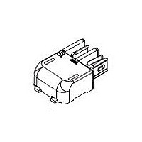
... Hermaphroditic Blade and Receptacle SMT Connectors. The contacts will accept stranded copper wire with a wire size range of 22--18 AWG. The contacts feature a locking lance to engage the housing and require no insertion tooling. Once terminated, the contacts are inserted into the BACK of the housings. The housings have single row cavities with a centerline spacing of 4 ...

Page 2

... Specifications Design Objective 108--2387 provides expected product performance and test information. Application Specification 114--13225 provides information on Hermaphroditic Blade and Receptacle Connectors. 2.5. Instructional Material The following list includes instruction sheets (408--series) that provide assembly procedures for product, operation, maintenance and repair of tooling ...

Page 3

... H. Wire Barrel Seam The wire barrel seam shall be closed adequately to confine all strands of the wire. There shall be no loose strands. Wire strands should not be embedded in the outside of the wire barrel. I. Locking Lance The locking lance shall not be deformed. Rev E 114- 13252 ...

Page 4

... Socket Contact Shown, Blade Contact Has Same Requirements Locking Lance Not Deformed Wire Barrel Crimp Width 0.10 Max. Wire Barrel Flash Section Twist and Roll There shall be no twist or roll in crimped portion that will impair usage of the contact. See Figure 4. Front of Contact ...

Page 5

... BACK of Housing 3.6. Keying, Engagement, and Disengagement A. Keying The housing cavity for the blade contact is keyed where by the blade contact can only be inserted in one orientation. Rev E Datum Line Figure 5 Contacts Locked in Place Figure 6 114- 13252 2 Max 2 Max 2 Max ...

Page 6

... A list of tooling recommendations and instructional material packaged with the tooling covering the full wire size range is provided in Figure Pull on Wire to Remove from Housing After Locking Lance is Released Figure 7 114- 13252 Push on Locking Latch Here to Release Rev E ...

Page 7

... Extraction tools are designed to release the locking lance inside the connector housing without damaging the housing or contacts. Customers may use their own extraction tools, in which case the tool must fit in a 1.10 x 0.70 mm opening in the housing. The tool must be long enough to release the locking lance which is located at a depth of 10. the housing. ...

Page 8

... WIRE CONDUCTOR MUST BE FLUSH WITH OR PROTRUDE SLIGHTLY FROM THE FRONT OF THE WIRE BARREL CONTACTS MUST BE LOCKED IN PLACE BOTH HOUSINGS MUST BE USED TO COMPLETE A CIRCUIT FIGURE 9. VISUAL AID 114- 13252 NO WIRE STRANDS MAY PROTRUDE IN WIRE BARREL SEAM LOCKING LANCE MUST NOT BE DEFORMED Rev E ...

Related keywords