166052-1 TE Connectivity, 166052-1 Datasheet

CONTACT, SOCKET, HDP-20

166052-1

Manufacturer Part Number
166052-1
Description
CONTACT, SOCKET, HDP-20
Manufacturer
TE Connectivity
Series
HDP-20r
Datasheet

Specifications of 166052-1

Connector Type
Contact, Crimp
Contact Material
Phosphor Bronze
Contact Termination
Crimp
Gender
Socket
Termination
RoHS Compliant
Termination Method
Crimp
Rohs Compliant
Yes
Product Type
Contact
Product Series
HDP-20 (Crimp Snap)
Termination Method To Wire/cable
Crimp
Wire Insulation Diameter (mm [in])
0.76 – 1.02 [0.030 – 0.040]
Insulation Support
Yes
Grade
Standard
Contact Retention In Housing
Crimp Snap-In
Solder Tail Contact Plating
Tin over Nickel
Pin Diameter (mm [in])
1.02 [0.040]
Wire Range (mm² [awg])
0.08 - 0.22 [28-24]
Contact Type
Socket
Contact Base Material
Phosphor Bronze
Contact Plating, Mating Area, Material
Conforms to IEC 807-3, Performance Level 2
Contact Size
20
Rohs/elv Compliance
RoHS compliant, ELV compliant
Lead Free Solder Processes
Not relevant for lead free process
Rohs/elv Compliance History
Always was RoHS compliant
Packaging Method
Strip
Packaging Quantity
12,500

Available stocks

Company
Part Number
Manufacturer
Quantity
Price
Part Number:
166052-1
Manufacturer:
TE
Quantity:
12 500
1. INTRODUCTION
This specification covers the requirements for the application of HD--20 Precision Formed Contacts. These
contacts are available in three snap--in types: crimp, posted, and solder cup. The crimp snap--in contacts are
available with or without an insulation support barrel for strain relief. The contacts accept a wire size range of
28 through 18 AWG and may be terminated to either stranded or solid wire.
After termination, these contacts are inserted into the cavities in the BACK of the connector housing and snap
into place. Assembled connectors containing these contacts are available and designed to meet requirements
of Military Specification MIL--C--24308.
When corresponding with TE Connectivity (TE) Personnel, use the terminology provided in this specification to
facilitate your inquiries for information. Basic terms and features of this product are provided in Figure 1.
2. REFERENCE MATERIAL
2.1. Revision Summary
Revisions to this application specification include:
E2011 Tyco Electronics Corporation, a TE Connectivity Ltd. Company
All Rights Reserved
TE logo is a trademark.
*Trademark. Other product names, logos, or company names might be trademarks of their respective owners.
NOTE
S
S
i
Updated document to corporate requirements
New logo
Locator Slot
All numerical values are in metric units [with U.S. customary units in brackets]. Dimensions are in millimeters [and
inches]. Unless otherwise specified, dimensions have a tolerance of +0.13 [+.005] and angles have a tolerance of +2_.
Figures and illustrations are for identification only and are not drawn to scale.
Typical Pin Contact
Stabilizer
Posted Contact
HD- 20 Precision
Formed Contacts
Transition
Flange
Snap - - In Crimp Contacts
TOOLING ASSISTANCE CENTER 1--800--722--1111
PRODUCT INFORMATION 1--800--522--6752
Crimp Contact
Insulation
Barrel
Figure 1
Pin Contact Without
Insulation Barrel
Wire Barrel
Typical Socket Contact
This controlled document is subject to change.
For latest revision and Regional Customer Service,
visit our website at www.te.com
Color Dot on Underside
of Wire Barrel
Solder Cup Contact
Application Specification
Solder Cup
114- - 10000
16 MAR 11
1 of 11
Rev U
LOC B

Related parts for 166052-1

166052-1 Summary of contents

Page 1

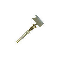
... Assembled connectors containing these contacts are available and designed to meet requirements of Military Specification MIL--C--24308. When corresponding with TE Connectivity (TE) Personnel, use the terminology provided in this specification to facilitate your inquiries for information. Basic terms and features of this product are provided in Figure 1. ...

Page 2

Customer Assistance Reference Product Base Part Number 66504 and Product Code 5899 are representative numbers of HD--20 Precision Formed Contacts. Use of these numbers will identify the product line and expedite your inquiries through a service network established to ...

Page 3

DO NOT nick, scrape, or cut the wire conductor during the stripping operation. CAUTION ! Discrete Wire Strip Length CONTACT POSITIONS CONTACT COLOR CODE WIRE SIZE WIRE SIZE (ON WIRE BARREL (ON WIRE BARREL RANGE ...

Page 4

B. Contact Crimp Features Figure 3 shows a typical contact as it should appear after crimping. Although a pin contact with insulation barrel is shown, the requirements apply equally to socket contacts and to contacts not having an insulation barrel. ...

Page 5

WIRE SIZE SIZE OF WIRE INSUL DIA WIRE INSUL DIA RANGE RANGE WIRE WIRE ACCEPTED (AWG) APPLIED 32 0.76--1.02 30 32--28 [.030 .040] [.030--.040 1.73 [.068] 26 Max Max 24 28 1.27--1.52 26 28--24 [.050 .060] [.050- - ...

Page 6

AUTOMATIC MACHINE WIRE CRIMP DIMENSIONS WIRE WIRE INSUL SIZE OF SIZE SIZE DIA DIA WIRE WIRE RANGE ACCEPTED APPLIED (AWG) 32 0.58--0.46 [.023--.018] 0.76--1.02 30 0.61--0.46 [.024--.018] 32--28 [.030 .040] [.030--.040] 28 0.63--0.51 [.025--.020] 28 0.66--0.76 [.026--.030] 1.73 [.068] 26 ...

Page 7

Crimped Contact Straightness A. Twist or Roll The crimped wire and insulation barrels must be aligned with the un--crimped portion of the contact to within the limit shown in Figure 4. Front of Contact (Pin or Socket) B. Straightness ...

Page 8

Consideration must be given to toxicity and other safety and health requirements as recommended in the Material DANGER Safety Data Sheet supplied by the solder cleaning solvent manufacturer. CLEANER NAME Alpha 2110 Bioact EC--7 Butyl Carbitol Isopropyl Alcohol Kester 5778 ...

Page 9

WIRE SIZE RANGE WIRE INSULATION (AWG) DIAMETER ACCEPTED 32--28 32 0.76--1.02 [.030--.040] 0 76-- 030- - 040] 1.73 [.068] Max 068] Max 1.27--1. [.050--.060] [.050--.060] 28--24 0.76--1.02 0.76 1.02 ...

Page 10

AMP MATIC Side Feed Stripper- - Crimper Model III Machine 1320895 (409- - 10012) AMPOMATOR CLS IV+ Lead- - Making Machine (409- - 5878) AMPOMATOR CLS Model III Lead- - Making Machine ...

Page 11

VISUAL AID Figure 8 shows a typical application of HD--20 Precision Formed Contacts. This illustration should be used by production personnel to ensure a correctly applied product. Applications which DO NOT appear correct should be inspected using the information ...

Related keywords