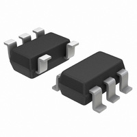
CAT5118TBI-00-T3 ON Semiconductor, CAT5118TBI-00-T3 Datasheet - Page 3

CAT5118TBI-00-T3
Manufacturer Part Number
CAT5118TBI-00-T3
Description
IC POT DIGITL 100K 32TAP SOT23-5
Manufacturer
ON Semiconductor
Datasheet
1.CAT5110TBI-50-T3.pdf
(12 pages)
Specifications of CAT5118TBI-00-T3
Taps
32
Resistance (ohms)
100K
Number Of Circuits
1
Temperature Coefficient
200 ppm/°C Typical
Memory Type
Volatile
Interface
2-Wire Serial, Up/Down
Voltage - Supply
2.7 V ~ 5.5 V
Operating Temperature
-40°C ~ 85°C
Mounting Type
Surface Mount
Package / Case
SOT-23-5, SC-74A, SOT-25
Resistance In Ohms
100K
Number Of Elements
1
# Of Taps
32
Resistance (max)
100KOhm
Power Supply Requirement
Single
Interface Type
Serial (2-Wire)
Single Supply Voltage (typ)
3.3/5V
Dual Supply Voltage (typ)
Not RequiredV
Single Supply Voltage (min)
2.7V
Single Supply Voltage (max)
5.5V
Dual Supply Voltage (min)
Not RequiredV
Dual Supply Voltage (max)
Not RequiredV
Operating Temp Range
-40C to 85C
Operating Temperature Classification
Industrial
Mounting
Surface Mount
Pin Count
5
Package Type
SOT-23
Lead Free Status / RoHS Status
Lead free / RoHS Compliant
Other names
CAT5118TBI-00-T3CT
2. Up/Down Toggle Rate: f
3. Typical settling times are dependent on end−to−end resistance.
4. Supply current measureed while changing wiper tap, f
5. Supply current measureed while wiper position is fixed.
DC PERFORMANCE
DIGITAL INPUTS
TIMING CHARACTERISTICS (Figures 7, 8)
POWER SUPPLY
Resolution
End−to−End Resistance (−00)
End−to−End Resistance (−50)
End−to−End Resistance (−10)
End−to−End Resistance Tempco
Ratiometric Resistance Tempco
Integral Nonlinearity
Differential Nonlinearity
Full−Scale Error
Zero−Scale Error
Wiper Resistance
Input High Voltage
Input Low Voltage
U/D Mode to CS Setup
CS to U/D Step Setup
CS to U/D Step Hold
U/D Step Low Period
U/D Step High Period
Up/Down Toggle Rate (Note 2)
Output Settling Time (Note 3)
Supply Voltage
Active Supply Current (Note 4)
Standby Supply Current (Note 5)
Table 3. ELECTRICAL CHARACTERISTICS
(V
DD
= 2.7 V to 5.5 V, V
Parameter
H
= V
TOGGLE
DD
, V
= 1 / t
L
= 0, T
SETTLE
A
Symbol
f
t
TOGGLE
= −40°C to +85°C. Typical values are at V
SETTLE
TC
DNL
V
INL
R
V
V
t
I
I
t
t
t
CU
t
DD
SB
CI
IC
IH
DD
IL
IH
W
IL
R
TOGGLE
configuration, C
configuration, C
http://onsemi.com
100 kW variable resistor
100 kW potentiometer
CAT5110/18/19
CAT5123/24/25
CAT5110/18/19
CAT5123/24/25
Conditions
V
= 1 MHz.
DD
3
= +5 V
L
L
= 10 pF
= 10 pF
DD
0.7 x V
= 2.7 V, T
Min
2.7
32
80
40
25
50
25
25
25
8
DD
A
= 25°C, unless otherwise noted.)
±0.5
±0.1
0.25
Typ
100
200
200
0.3
50
10
30
80
5
1
1
0.3 x V
Max
120
300
600
200
5.5
60
12
±1
±1
25
1
1
DD
ppm/°C
ppm/°C
Units
Taps
MHz
LSB
LSB
LSB
LSB
kW
mA
mA
ns
ns
ns
ns
ns
ms
W
V
V
V


