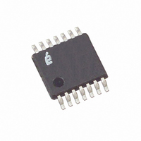
X93256UV14I-2.7T1 Intersil, X93256UV14I-2.7T1 Datasheet - Page 2

X93256UV14I-2.7T1
Manufacturer Part Number
X93256UV14I-2.7T1
Description
IC XDCP DUAL 32-TAP 50K 14-TSSOP
Manufacturer
Intersil
Series
XDCP™r
Datasheet
1.X93256UV14IZ-2.7.pdf
(7 pages)
Specifications of X93256UV14I-2.7T1
Taps
32
Resistance (ohms)
50K
Number Of Circuits
2
Temperature Coefficient
35 ppm/°C Typical
Memory Type
Non-Volatile
Interface
Up/Down (3-Wire)
Voltage - Supply
2.7 V ~ 5.5 V
Operating Temperature
-40°C ~ 85°C
Mounting Type
Surface Mount
Package / Case
14-TSSOP
Resistance In Ohms
50K
Lead Free Status / RoHS Status
Contains lead / RoHS non-compliant
Block Diagram
Pin Descriptions
(INC
(U/D
TSSOP
DEVICE SELECT
INCREMENT
(CS
UP/DOWN
10
11
12
13
14
1
1
2
3
4
5
6
7
8
9
1
1
AND INC
AND U/D
AND CS
SYMBOL
2
2
2
)
INC
U/D
INC
U/D
)
)
R
R
V
CS
R
V
CS
R
R
R
V
W1
W2
CC
SS
CC
H2
H1
L1
L2
1
2
GENERAL DESCRIPTION
2
2
1
1
(SUPPLY VOLTAGE)
30k
V
CONTROL
SS
MEMORY
R
terminal of a mechanical potentiometer.
R
minimum voltage is V
the terminal in relation to wiper movement direction selected by the U/D input.
Chip Select 1 (CS
in nonvolatile memory when CS
complete, the first potentiometer of the X93256 will be placed in the low power standby mode until the first potentiometer
is selected once again.
Increment 2 (INC
potentiometer and either increment or decrement the counter in the direction indicated by the logic level on the U/D
input.
Up/Down 2 (U/D
counter for the second potentiometer is incremented or decremented.
R
minimum voltage is V
the wiper terminal for the second potentiometer in relation to the wiper movement direction selected by the U/D
Ground.
R
terminal of a mechanical potentiometer.
R
minimum voltage is V
the wiper terminal for the second potentiometer in relation to the wiper movement direction selected by the U/D
Chip Select 2 (CS
stored in nonvolatile memory when CS
complete, the second potentiometer of the X93256 will be placed in the low power standby mode until the second
potentiometer is selected once again.
Supply Voltage.
Increment 1(INC
potentiometer and either increment or decrement the counter in the direction indicated by the logic level on the U/D
input.
Up/Down 1 (U/D
counter for the first potentiometer is incremented or decremented.
R
minimum voltage is V
the wiper terminal for the first potentiometer in relation to the wiper movement direction selected by the U/D
W1
W2
L1
H2
L2
H1
AND
(GROUND)
. The R
. The R
. The R
. The R
. The R
. The R
2
H1
H2
H
H
W2
W1
2 and R
1 and R
and R
and R
pin of the X93256 is the wiper terminal of the first potentiometer, which is equivalent to the movable
pin of the X93256 is the wiper terminal of the second potentiometer, which is equivalent to the movable
2
1
1
2
). The U/D
). The U/D
1
). The INC
2
). The INC
). The first potentiometer is selected when the CS
). The second potentiometer is selected when the CS
L1
L2
L2
L1
SS
SS
SS
SS
R
R
R
R
R
R
pins of the X93256 are equivalent to the fixed terminals of a mechanical potentiometer. The
pins of the X93256 are equivalent to the fixed terminals of a mechanical potentiometer. The
pins of the X93256 are equivalent to the fixed terminals of a mechanical potentiometer. The
pins of the X93256 are equivalent to the fixed terminals of a mechanical potentiometer. The
H1
H2
W1
L2
L1
and the maximum is V
and the maximum is V
and the maximum is V
and the maximum is V
W2
2
1
1
2
input controls the direction of the second potentiometer wiper movement and whether the
input controls the direction of the first potentiometer wiper movement and whether the
input is negative-edge triggered. Toggling INC
input is negative-edge triggered. Toggling INC
1
is returned HIGH while the INC
V
V
INC
U/D
CS
CC
SS
2
is returned HIGH while the INC
X93256
1
1
1
CC
CC
CC
CC
BRIEF DESCRIPTION
NONVOLATILE
STORE AND
. The terminology of R
. The terminology of R
. The terminology of R
. The terminology of R
CIRCUITRY
UP/DOWN
COUNTER
CONTROL
MEMORY
RECALL
5-BIT
5-BIT
DETAILED SINGLE POTENTIOMETER DESCRIPTION
1
input is also HIGH. After the store operation is
DECODER
1
THIRTY
input is LOW. The current counter value is stored
TWO
ONE
2
OF
H1
H2
H2
H1
input is also HIGH. After the store operation is
2
input is LOW. The current counter value is
and R
and R
and R
and R
31
30
29
28
1
2
1
0
2
will move the wiper of the first
will move the wiper of the second
L1
L2
L2
L1
references the relative position of
references the relative position of
references the relative position of
references the relative position of
TRANSFER
GATES
RESISTOR
ARRAY
February 1, 2008
1
input.
R
2
2
R
FN8188.2
L1
input.
input.
H1
R
W
2
1


