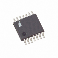
X93255UV14IT1 Intersil, X93255UV14IT1 Datasheet - Page 3

X93255UV14IT1
Manufacturer Part Number
X93255UV14IT1
Description
IC XDCP DUAL 32-TAP 50K 14-TSSOP
Manufacturer
Intersil
Series
XDCP™r
Datasheet
1.X93255UV14I.pdf
(7 pages)
Specifications of X93255UV14IT1
Taps
32
Resistance (ohms)
50K
Number Of Circuits
2
Temperature Coefficient
35 ppm/°C Typical
Memory Type
Non-Volatile
Interface
Up/Down (3-Wire)
Voltage - Supply
4.5 V ~ 5.5 V
Operating Temperature
-40°C ~ 85°C
Mounting Type
Surface Mount
Package / Case
14-TSSOP
Resistance In Ohms
50K
Lead Free Status / RoHS Status
Contains lead / RoHS non-compliant
Potentiometer Characteristics
Absolute Maximum Ratings
Voltage on CS, INC, U/D, R
Maximum resistor current . . . . . . . . . . . . . . . . . . . . . . . . . . . . . 2mA
Recommended Operating Conditions
Temperature Range
Supply Voltage
CAUTION: Do not operate at or near the maximum ratings listed for extended periods of time. Exposure to such conditions may adversely impact product reliability and
result in failures not covered by warranty.
NOTES:
1. Absolute linearity is utilized to determine actual wiper resistance vs expected resistance = (R
2. Relative linearity is a measure of the error in step size between taps = R
3. 1 Ml = Minimum Increment = R
4. Typical values are for T
5. Limits established by characterization and are not production tested.
6. When performing multiple write operations, V
7. Parts are 100% tested at +25°C. Over-temperature limits established by characterization and are not production tested.
with respect to V
Industrial. . . . . . . . . . . . . . . . . . . . . . . . . . . . . . . . .-40°C to +85°C
V
C
SYMBOL
CC
±1 Ml Maximum. n = 1 .. 29 only
H
R
/C
R
V
TOT
I
. . . . . . . . . . . . . . . . . . . . . . . . . . . . . . . . . .5V ±10% (Note 6)
W
W
R
L
/C
W
End-to-End Resistance
R
Power Rating
Noise
Wiper Resistance
Wiper Current
Resolution
Absolute Linearity (Note 1)
Relative Linearity (Note 2)
R
Potentiometer Capacitances
SS
H
TOTAL
, R
. . . . . . . . . . . . . . . . . . . . . . . . . . -1V to +6.5V
L
Terminal Voltages
Temperature Coefficient
H
A
, R
= +25°C and nominal supply voltage.
L
PARAMETER
3
and V
TOT
/31.
CC
Over recommended operating conditions, unless otherwise specified.
CC
must not decrease by more than 150mV from its initial value.
R
Ref: 1kHz (Note 5)
(Note 5)
(Note 5)
R
R
(Notes 5)
See “Circuit #2 SPICE Macro Model”
on page 4
TOTAL
H(n)(actual)
H(n+1 -
TEST CONDITIONS/NOTES
X93255
= 50kΩ (Note 5)
[R
H(n)+MI
- R
H(n+1)
Thermal Information
Temperature under bias. . . . . . . . . . . . . . . . . . . . . .-65°C to +135°C
Storage temperature . . . . . . . . . . . . . . . . . . . . . . . .-65°C to +150°C
Lead temperature (soldering 10s) . . . . . . . . . . . . . . . . . . . . . +300°C
Maximum reflow temperature (40s) . . . . . . . . . . . . . . . . . . . . +240°C
H(n)(expected)
]
- [R
H(n)
+ Ml] = ±0.5 Ml, n = 1 .. 29 only.
H(n)
(actual) - R
(Note 7)
37.5
MIN
0
H(n)
10/10/25
(Note 4)
(expected)) =
-120
TYP
±35
50
3
(Note 7)
MAX
1000
62.5
V
±0.5
0.6
±1
CC
1
February 4, 2008
(Note 6)
(Note 6)
(Note 3)
(Note 3)
ppm/°C
UNIT
FN8187.1
dBV
mΩ
mA
kΩ
MI
MI
pF
%
V
Ω


