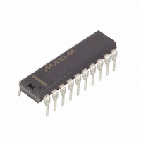
DS1802 Maxim Integrated Products, DS1802 Datasheet - Page 15

DS1802
Manufacturer Part Number
DS1802
Description
IC POT DL AUDIO TAP W/PB 20-DIP
Manufacturer
Maxim Integrated Products
Datasheet
1.DS1802.pdf
(17 pages)
Specifications of DS1802
Taps
64
Resistance (ohms)
45K
Number Of Circuits
2
Temperature Coefficient
750 ppm/°C Typical
Memory Type
Volatile
Interface
3-Wire Serial
Voltage - Supply
2.7 V ~ 5.5 V
Operating Temperature
-40°C ~ 85°C
Mounting Type
Through Hole
Package / Case
20-DIP (0.300", 7.62mm)
Resistance In Ohms
45K
Lead Free Status / RoHS Status
Contains lead / RoHS non-compliant
Available stocks
Company
Part Number
Manufacturer
Quantity
Price
Part Number:
DS1802
Manufacturer:
MAXIM/美信
Quantity:
20 000
Company:
Part Number:
DS1802+
Manufacturer:
Maxim
Quantity:
125
Company:
Part Number:
DS1802E/TR
Manufacturer:
VISHAY
Quantity:
5 000
Company:
Part Number:
DS1802S+
Manufacturer:
VISHAY
Quantity:
3 938
Company:
Part Number:
DS1802Z-010
Manufacturer:
DALLAS
Quantity:
6
AC ELECTRICAL CHARACTERISTICS
AC ELECTRICAL CHARACTERISTICS (PUSHBUTTON INPUTS)
NOTES:
1. All voltages are referenced to ground.
2. Valid for V
3. Both UCx and DCx inputs are internally pulled up with a 50K
4. Capacitance values apply at 25 C.
5. Input pulse width is the minimum time required for an input to cause an increment or decrement. If
6. Inter-channel matching is used to determine the relative voltage difference in dB between the same
CLK Frequency
Width of CLK Pulse
Data Setup Time
Data Hold Time
Propagation Delay Time
Propagation Delay Time
CLK Rise Time
PARAMETER
Single Pulse Input
Repetitive Input Pulse High Time
Continuous Input Pulse
RST
RST
RST
the UCx or DCx inputs is held active for longer than 1 second, subsequent increments or decrements
will occur on 100 ms intervals until the inputs UCx, DCx are released to V
pushbutton control is 30%.
tap position on each potentiometer. The DS1802 is specified for 0.5 dB inter-channel matching.
Low to High Level
Clock to Output
Low to High Level
High to Clock Input High
Low to Clock Input High
Inactive
PARAMETER
CC
=5V only.
SYMBOL
t
f
t
t
t
t
t
t
CDH
CLK
PLH
PLH
t
HLT
t
RLT
CH
DC
CC
CR
SYMBOL
t
t
t
CPW
HPW
CCP
15 of 17
MIN
200
DC
50
30
10
50
50
MIN
1
1
1
(-40 C to +85 C; V
(-40 C to +85 C; V
TYP
TYP
resistance.
MAX
MAX
DC
DC
DC
10
50
50
50
IH
CC
CC
. Timing tolerances for
UNITS
UNITS
=2.7V to 5.5V)
=2.7V to 5.5V)
MHz
ms
ms
ns
ns
ns
ns
ns
ns
ns
ns
ns
s
NOTES
NOTES
3,5,13
3,5,13
3,5,13
10,13
10,13
10,13
10,13
10,13
10,13
10,13
10,13
10,13
10,13
DS1802


