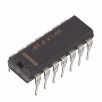
DS1801 Maxim Integrated Products, DS1801 Datasheet

DS1801
Specifications of DS1801
Available stocks
Related parts for DS1801
DS1801 Summary of contents
Page 1
... No Connect DESCRIPTION The DS1801 is a dual audio taper potentiometer having logarithmic resistive characteristics over the device range. Each potentiometer provides 65 wiper positions with increment per step and device mute. The 3-wire serial interface, using a CPU, provides the user the ability of reading or writing exact wiper positions of the two potentiometers ...
Page 2
... CPU-controlled applications and allows the potentiometer’s exact wiper position to be read or written. environments. Figure 1 presents a block diagram of the DS1801. As shown, the inputs from the 3-wire serial interface drive a command/control unit. The command/control unit interprets these inputs for control of the two potentiometers. ...
Page 3
... Bit 15, like bit “don’t care” and will not affect operation of the DS1801. Data for the DS1801 is transmitted LSB first starting with bit 0. A complete transmission of 16 bits of data is required to insure proper setting of each potentiometer’s wiper. An incomplete transmission may result in undesired wiper settings ...
Page 4
... TIMING DIAGRAMS Figure DS1801 ...
Page 5
... CASCADE OPERATION A feature of the DS1801 is the ability to control multiple devices from a single processor. Multiple DS1801s can be linked or daisy-chained as shown in Figure data bit is entered into the I/O shift register of the DS1801, bit 0 of the I/O shift register will appear at the nanoseconds. The C output of the DS1801 can be used to drive the D input of another DS1801 ...
Page 6
... TYPICAL SUPPLY CURRENT VS. SERIAL CLOCK RATE Figure DS1801 ...
Page 7
... SYMBOL MIN TYP -0.5 IL L,H,W GND-0.5 AGND GND-0 SYMBOL MIN TYP 400 DS1801 (- +85 C) MAX UNITS NOTES 5 +0.5 V 1,2 CC +.08 V 1 GND+0 =2.7V to 5.5V) CC MAX UNITS NOTES -. ...
Page 8
... Mute Control Active CAPACITANCE PARAMETER Input Capacitance Output Capacitance SYMBOL MIN TYP -20 -1 -0.5 -0.25 f 700 CUTOFF 750 THD 0.002 2.2 -90 -100 Mute - SYMBOL MIN TYP OUT DS1801 =2.7V to 5.5V) CC MAX UNITS NOTES + +0.5 4 +0.25 dB 5,12 kHz ppm RMS =2.7V to 5.5V) CC ...
Page 9
... Capacitance values apply at 25°C. 4. Inter-channel matching is used to determine the relative voltage difference in dB between the same tap position on each potentiometer. The DS1801 is specified for 0.5 dB inter-channel matching. 5. Tap-to-tap tolerance is used to determine the change in voltage between successive tap positions. The DS1801 is specified for 0.25 dB tap-to-tap tolerance. ...
Page 10
... DIGITAL OUTPUT LOAD Figure 6 INTERNAL GROUND CONNECTIONS Figure 7 NOTE: GND and AGND must be tied to the same voltage level. DS1801 ORDERING INFORMATION ORDERING INFORMATION DS1801 DS1801E 14L TSSOP (173-mil) DS1801S 16L SOIC (300-mil) PACKAGE OPERATING TEMPERATURE 14L DIP -40°C to +85°C -40°C to +85°C -40° ...


