DS1848B-010/T&R Maxim Integrated Products, DS1848B-010/T&R Datasheet - Page 6

DS1848B-010/T&R
Manufacturer Part Number
DS1848B-010/T&R
Description
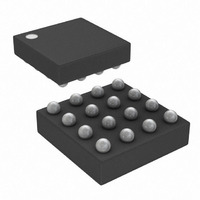
IC RES/MEM TEMP 10/10K 16-BGA
Manufacturer
Maxim Integrated Products
Datasheet
1.DS1848E-010TR.pdf
(17 pages)
Specifications of DS1848B-010/T&R
Taps
256
Resistance (ohms)
10K
Number Of Circuits
2
Temperature Coefficient
850 ppm/°C Typical
Memory Type
Non-Volatile
Interface
I²C, 2-Wire Serial
Voltage - Supply
3 V ~ 5.5 V
Operating Temperature
-40°C ~ 95°C
Mounting Type
Surface Mount
Package / Case
16-CSBGA
Resistance In Ohms
10K
Lead Free Status / RoHS Status
Contains lead / RoHS non-compliant
Available stocks
Company
Part Number
Manufacturer
Quantity
Price
Company:
Part Number:
DS1848B-010/T&RDS1848B-010/T&R
Manufacturer:
Maxim Integrated
Quantity:
10 000
PROGRAMMING THE LOOK-UP TABLE (LUT)
The following equation can be used to determine which resistor position setting, 00h – FFh, should be
written in the LUT to achieve a given resistance at a specific temperature.
DS1848-050
a = 3.78964 for the 50kW resistor
a = 19.74866 for the 10kW resistor
DS1848-010
a = 8.394533 for both 10kW resistors
R = resistance desired at the output terminal
C = temperature in degrees Celsius
u, v, w, x, y, and z are calibration constants programmed into each of the corresponding look-up tables.
Their addresses and LSB values are given in Table 1 below. Resistor 1 variables are found in Look-Up
table 1 of the EEPROM, and Resistor 2 variables are found in Look-Up Table 2. After these values are
read, they should be overwritten with the appropriate temperature specific resistance settings. Copies of
these values can also be found in the User EEPROM memory.
LOOK-UP VARIABLE ADDRESSES Table1
When shipped from the factory, all other memory locations in the LUTs are programmed to FFh (except
bytes 00h-07h of Table 1 and 2 which may be factory programmed to values other than FFh).
Note: Memory locations 44h – 47h, which cover the temperature range (+96ºC to +102ºC), are outside
of the specified operating temperature range (-40ºC to +95ºC). However, the values stored in these
locations will act as valid resistance settings if the temperature exceeds +95ºC. Therefore, Dallas
Semiconductor recommends that the user program a resistance value into all LUT locations. Failure to do
so will result in the part being set to the default value.
pos
LUT (HEX)
Address in
(
a
2A – 2B
2C – 2D
2E – 2F
28 – 29
30 – 31
32 – 33
,
R
,
C
)
=
R
( )
-
x
u
·
·
Variable
[
1
[
1
+
+
w
u
v
x
y
z
y
v
·
·
(
C
(
C
-
-
25
25
10
LSB
10
10
10
)
2
2
)
+
-8
-8
-10
+
-6
-9
-7
z
w
·
·
(
C
(
C
-
-
25
25
)
2
)
]
2
]
-
a
6 of 17


