PIC10F220-E/OT Microchip Technology, PIC10F220-E/OT Datasheet - Page 48
PIC10F220-E/OT
Manufacturer Part Number
PIC10F220-E/OT
Description
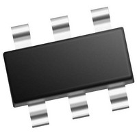
384B Flash, 16B RAM, 4 I/O, 8bit ADC 6 SOT-23 BAG
Manufacturer
Microchip Technology
Series
PIC® 10Fr
Datasheet
1.PIC10F220-IMC.pdf
(86 pages)
Specifications of PIC10F220-E/OT
Processor Series
PIC10F
Core
RISC
Data Bus Width
8 bit
Program Memory Type
Flash
Program Memory Size
256 B
Data Ram Size
16 B
Interface Type
RS-232, USB
Maximum Clock Frequency
8 MHZ
Number Of Programmable I/os
4
Number Of Timers
1
Maximum Operating Temperature
+ 125 C
Mounting Style
SMD/SMT
Package / Case
SOT-23-6
Operating Temperature Range
- 40 C to + 125 C
Processor To Be Evaluated
PIC10F220
Supply Current (max)
100 nA
Core Processor
PIC
Core Size
8-Bit
Speed
8MHz
Connectivity
-
Peripherals
POR, WDT
Number Of I /o
4
Eeprom Size
-
Ram Size
16 x 8
Voltage - Supply (vcc/vdd)
2 V ~ 5.5 V
Data Converters
A/D 2x8b
Oscillator Type
Internal
Operating Temperature
-40°C ~ 125°C
Lead Free Status / Rohs Status
Details


PIC10F220/222
BTFSS
Syntax:
Operands:
Operation:
Status Affected: None
Description:
CALL
Syntax:
Operands:
Operation:
Status Affected: None
Description:
CLRF
Syntax:
Operands:
Operation:
Status Affected: Z
Description:
DS41270E-page 46
Bit Test f, Skip if Set
[ label ] BTFSS f,b
0 ≤ f ≤ 31
0 ≤ b < 7
skip if (f<b>) = 1
If bit ‘b’ in register ‘f’ is ‘1’, then the
next instruction is skipped.
If bit ‘b’ is ‘1’, then the next instruc-
tion fetched during the current
instruction execution, is discarded
and a NOP is executed instead,
making this a two-cycle instruction.
[ label ] CALL k
0 ≤ k ≤ 255
(PC) + 1→ Top of Stack;
k → PC<7:0>;
(Status<6:5>) → PC<10:9>;
0 → PC<8>
Subroutine call. First, return
address (PC + 1) is pushed onto
the stack. The eight-bit immediate
address is loaded into PC bits
<7:0>. The upper bits PC<10:9>
are loaded from STATUS<6:5>,
PC<8> is cleared. CALL is a two-
cycle instruction.
Clear f
[ label ] CLRF
0 ≤ f ≤ 31
00h → (f);
1 → Z
The contents of register ‘f’ are
cleared and the Z bit is set.
Subroutine Call
f
CLRW
Syntax:
Operands:
Operation:
Status Affected: Z
Description:
CLRWDT
Syntax:
Operands:
Operation:
Status Affected: TO, PD
Description:
COMF
Syntax:
Operands:
Operation:
Status Affected: Z
Description:
Clear W
[ label ] CLRW
None
00h → (W);
1 → Z
The W register is cleared. Zero bit
(Z) is set.
Clear Watchdog Timer
[ label ] CLRWDT k
None
00h → WDT;
0 → WDT prescaler (if assigned);
1 → TO;
1 → PD
The CLRWDT instruction resets the
WDT. It also resets the prescaler, if
the prescaler is assigned to the
WDT and not Timer0. Status bits
TO and PD are set.
Complement f
[ label ] COMF
0 ≤ f ≤ 31
d ∈ [0,1]
(f) → (dest)
The contents of register ‘f’ are
complemented. If ‘d’ is ‘0’, the
result is stored in the W register. If
‘d’ is ‘1’, the result is stored back in
register ‘f’.
© 2007 Microchip Technology Inc.
f,d
Related parts for PIC10F220-E/OT
Image
Part Number
Description
Manufacturer
Datasheet
Request
R

Part Number:
Description:
384B Flash, 16B RAM, 4 I/O, 8bit ADC 6 SOT-23 BAG
Manufacturer:
Microchip Technology
Datasheet:

Part Number:
Description:
IC PIC MCU FLASH 256X12 8DFN
Manufacturer:
Microchip Technology
Datasheet:
Part Number:
Description:
IC PIC MCU FLASH 256X12 8DFN
Manufacturer:
Microchip Technology
Datasheet:
Part Number:
Description:
IC PIC MCU FLASH 256X12 8DIP
Manufacturer:
Microchip Technology
Datasheet:

Part Number:
Description:
Microcontroller
Manufacturer:
Microchip Technology
Datasheet:
Part Number:
Description:
768B Flash, 23B RAM, 4 I/O, 8bit ADC 6 SOT-23 BAG
Manufacturer:
Microchip Technology
Datasheet:
Part Number:
Description:
768B Flash, 23B RAM, 4 I/O, 8bit ADC 6 SOT-23 BAG
Manufacturer:
Microchip Technology
Datasheet:

Part Number:
Description:
PIC10F PROGRAMMER ADAPTER (SOT-23), PICKIT
Manufacturer:
Microchip Technology Inc.
Part Number:
Description:
Manufacturer:
Microchip Technology Inc.
Datasheet:
Part Number:
Description:
Manufacturer:
Microchip Technology Inc.
Datasheet:
Part Number:
Description:
Manufacturer:
Microchip Technology Inc.
Datasheet:
Part Number:
Description:
Manufacturer:
Microchip Technology Inc.
Datasheet: