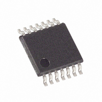
MAX5415EUD Maxim Integrated Products, MAX5415EUD Datasheet - Page 9

MAX5415EUD
Manufacturer Part Number
MAX5415EUD
Description
IC POT DUAL DGTL 256TAP 14-TSSOP
Manufacturer
Maxim Integrated Products
Datasheet
1.MAX5415EUD.pdf
(11 pages)
Specifications of MAX5415EUD
Taps
256
Resistance (ohms)
100K
Number Of Circuits
2
Temperature Coefficient
35 ppm/°C Typical
Memory Type
Volatile
Interface
SPI, 3-Wire Serial
Voltage - Supply
2.7 V ~ 5.5 V
Operating Temperature
-40°C ~ 85°C
Mounting Type
Surface Mount
Package / Case
14-TSSOP
Resistance In Ohms
100K
Lead Free Status / RoHS Status
Contains lead / RoHS non-compliant
Available stocks
Company
Part Number
Manufacturer
Quantity
Price
Company:
Part Number:
MAX5415EUD
Manufacturer:
MAXIM
Quantity:
84
Company:
Part Number:
MAX5415EUD
Manufacturer:
MAXIM
Quantity:
127
Part Number:
MAX5415EUD
Manufacturer:
MAXIM/美信
Quantity:
20 000
Company:
Part Number:
MAX5415EUD+
Manufacturer:
Maxim
Quantity:
2 235
Part Number:
MAX5415EUD+
Manufacturer:
MAXIM/美信
Quantity:
20 000
Company:
Part Number:
MAX5415EUD+T
Manufacturer:
MAXIM
Quantity:
75
Part Number:
MAX5415EUD+T
Manufacturer:
MAXIM/美信
Quantity:
20 000
In
are shown with the MAX6160 to make an adjustable
voltage reference. In this circuit, the H
MAX5413/MAX5414/MAX5415 is connected to the
OUT pin of the MAX6160, the L
MAX5414/MAX5415 is connected to GND, and the W
pin of the MAX5413/MAX5414/MAX5415 is connected
to the ADJ pin of the MAX6160. The MAX5413/
MAX5414/MAX5415 allow precise setting of the voltage
reference output. A low 5ppm/°C ratiometric tempco
allows a very stable adjustable voltage overtemperature.
Dual, 256-Tap, Low-Drift, Digital Potentiometers
Figure 4. Serial Data Format
Figure 5. I to V Converter
ADDRESS
First Bit In
B0 (A0)
Figure 7, the MAX5413/MAX5414/MAX5415
(MSB)
V
B1 (D7)
0
Adjustable Voltage Reference
/ I
_______________________________________________________________________________________
R3
S
= R
3
(1 + R
2
+5V
/R
W
1
X
) + R
B2 (D6)
2
MAX4250
X
H
L
X
pin of the MAX5413/
X
MAX5413
MAX5414
MAX5415
B3 (D5)
X
pin of the
V
0
R2
DATA WORD
X
B4 (D4)
Figure 6a. Adjustable Gain Circuit
Figure 6b. Adjustable Gain Circuit Using 3-Terminal
Potentiometer
B5 (D3)
L
X
V
in 14-Pin TSSOP
V
IN
IN
H
X
MAX5413
MAX5414
MAX5415
B6 (D2)
L
X
W
X
W
H
X
V
X
CC
V
CC
B7 (D1)
MAX5413
MAX5414
MAX5415
V
OUT
V
OUT
Last Bit In
B8 (D0)
(LSB)
9


