DS1866 Maxim Integrated Products, DS1866 Datasheet
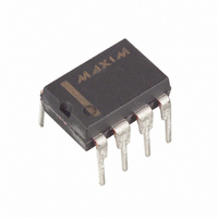
IC POT TRIM LOG 2.7-5.5V 8-DIP

DS1866

Manufacturer Part Number
DS1866
Description
IC POT TRIM LOG 2.7-5.5V 8-DIP
Manufacturer
Maxim Integrated Products
Datasheet

Specifications of DS1866

Taps
8
Resistance (ohms)
10K
Number Of Circuits
1
Temperature Coefficient
750 ppm/°C Typical
Memory Type
Volatile
Interface
3-Input Parallel
Voltage - Supply
2.7 V ~ 5.5 V
Operating Temperature
-40°C ~ 85°C
Mounting Type
Through Hole
Package / Case
8-DIP (0.300", 7.62mm)
Resistance In Ohms
10K
Lead Free Status / RoHS Status
Contains lead / RoHS non-compliant

Available stocks

Company
Part Number
Manufacturer
Quantity
Price
Company:
Part Number:
DS1866
Quantity:
780
Part Number:
DS1866Z
Manufacturer:
DALLAS
Quantity:
20 000
Part Number:
DS1866Z+
Manufacturer:
Renesas
Quantity:
320
Part Number:
DS1866Z+T&R
Manufacturer:
MAXIM/美信
Quantity:
20 000
FEATURES
§ Single 8-position Log Trimmer Potentiometer
§ Operates from 2.7V to 5.5V supplies
§ Parallel interface control: P0, P1, P2
§ Standard Resistance Value: 10 k
§ 8-pin DIPs; 8-pin (150) SOICs
§ Operating Temperature Range:
DESCRIPTION
The DS1866 Log Trimmer Potentiometer is a single volatile digital potentiometer having eight positions
with a 5-dB resolution per step. The device provides an ideal method for low-cost trimming or volume
control using a CPU or manual control input. The device’ s wiper position is set to one of eight positions
by a 3-terminal parallel port. The value of the wiper position is determined by the P0, P1, and P2 port
pins.
The DS1866 is available as a 10k potentiometer and is available in an industrial temperature grade.
Additionally, the DS1866 will operate from 3V or 5V supplies and is ideal for portable applications
requiring low standby current. Two packaging options are available and include the 8-pin (300-mil) DIP,
8-pin (150-mil) SOIC.
www.dalsemi.com
5-dB/step
- Industrial: -40°C to +85°C
1 of 5
PIN ASSIGNMENT
PIN DESCRIPTION
H
L
W
V
P0
P1
P2
GND
Log Trimmer Potentiometer
CC
See Mech. Drawings Section
GND
GND
P0
P0
P1
P1
8-Pin SOIC (150-mil)
H
H
8-Pin DIP (300-mil)
1
1
2
3
4
2
3
4
- High End of Resistor
- Low End of Resistor
- Wiper Terminal
- 3V or 5V Power Supply Input
- Position Select - Bit 0
- Position Select - Bit 1
- Position Select - Bit 2
- Ground
8
7
6
5
8
7
6
5
L
P2
L
P2
W
V
V
W
CC
CC
DS1866
102199

Related parts for DS1866

DS1866 Summary of contents

Page 1

... The DS1866 is available as a 10k potentiometer and is available in an industrial temperature grade. Additionally, the DS1866 will operate from supplies and is ideal for portable applications requiring low standby current. Two packaging options are available and include the 8-pin (300-mil) DIP, 8-pin (150-mil) SOIC. ...

Page 2

... W-terminal whose position is controlled via a 3-terminal parallel port consisting of input signals P0, P1, and P2. A block diagram of the DS1866 is shown in Figure 1. Wiper position setting of the DS1866 is determined by the states of the P0, P1, and P2 input terminals. Table 1 below outlines position setting versus value of the parallel port inputs. A Position-0 setting places the wiper position at the L-terminal of the potentiometer and provides attenuation ...

Page 3

... One Time Programmability (OTP). The DS1866 can be easily used as an OTP device. This can be accomplished by terminating the P0, P1 desired logic levels during system manufacturing. On power up, the value of P0, P1, and P2 will then set the wiper position setting of the DS1866. DS1866 BLOCK DIAGRAM Figure 1 ...

Page 4

... GND +0 2.7V to 5.5V) CC MAX UNITS NOTES 400 µA +1 µA 1000 1 mA µA 50 µA = 2.7V to 5.5V) CC MAX UNITS NOTES +20 % +1.0 dB +1.0 dB MHz ppm/°C (25° 2.7V to 5.5V) CC MAX UNITS NOTES 2.7V to 5.5V) CC MAX UNITS NOTES 500 ns 102199 DS1866 ...

Page 5

... However, this change will not exceed ±20% of the nominal resistor value of the part. 8. Absolute tolerance is used to compare measured wiper voltage versus expected wiper voltage as determined by wiper position. The DS1866 is specified to provide an absolute tolerance of ±1.0 dB. 9. Tap-to-tap tolerance is used to determine the change in voltage between successive tap positions. The DS1866 is specified to provide a tap-to-tap tolerance specification of ± ...

Related keywords