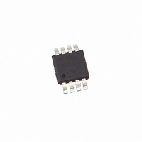
X9317WM8I-2.7 Intersil, X9317WM8I-2.7 Datasheet - Page 8

X9317WM8I-2.7
Manufacturer Part Number
X9317WM8I-2.7
Description
IC DIGITAL POT 10K 100TP 8MSOP
Manufacturer
Intersil
Series
XDCP™r
Datasheet
1.X9317WP.pdf
(15 pages)
Specifications of X9317WM8I-2.7
Taps
100
Resistance (ohms)
10K
Number Of Circuits
1
Temperature Coefficient
300 ppm/°C Typical
Memory Type
Non-Volatile
Interface
Up/Down (3-Wire)
Voltage - Supply
2.7 V ~ 5.5 V
Operating Temperature
-40°C ~ 85°C
Mounting Type
Surface Mount
Package / Case
8-MSOP, Micro8™, 8-uMAX, 8-uSOP,
Resistance In Ohms
10K
Number Of Elements
1
# Of Taps
100
Resistance (max)
10KOhm
Power Supply Requirement
Single
Interface Type
Serial (3-Wire)
Single Supply Voltage (typ)
3.3/5V
Dual Supply Voltage (typ)
Not RequiredV
Single Supply Voltage (min)
2.7V
Single Supply Voltage (max)
5.5V
Dual Supply Voltage (min)
Not RequiredV
Dual Supply Voltage (max)
Not RequiredV
Operating Temp Range
-40C to 85C
Operating Temperature Classification
Industrial
Mounting
Surface Mount
Pin Count
8
Package Type
MSOP
Lead Free Status / RoHS Status
Contains lead / RoHS non-compliant
Power-up and Down Requirements
The recommended power-up sequence is to apply V
first, then the potentiometer voltages. During power-up, the
data sheet parameters for the DCP do not fully apply until
AC Timing
Typical Performance Characteristic
INC
U/D
CS
R
W
t
CI
t
IW
t
IL
t
8
ID
FIGURE 1. TYPICAL TOTAL RESISTANCE TEMPERATURE COEFFICIENT
t
CYC
-100
-150
-200
-250
-300
-350
t
IH
-50
0
-55
-45 -35 -25 -15 -5 5 15 25 35
t
DI
CC
t
IC
MI
/V
SS
(3)
TEMPERATURE (°C)
X9317
t
1ms after V
always in effect. In order to prevent unwanted tap position
changes, or an inadvertent store, bring the CS and INC high
before or concurrently with the V
45 55 65 75 85 95 105115 125
CPHS
CC
t
F
reaches its final value. The V
90%
10%
90%
CC
t
R
pin on power-up.
t
CPHNS
CC
December 16, 2009
ramp spec is
FN8183.6


