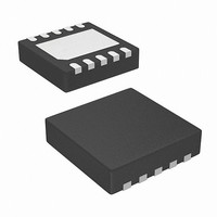
ISL22416UFRT10Z Intersil, ISL22416UFRT10Z Datasheet - Page 4

ISL22416UFRT10Z
Manufacturer Part Number
ISL22416UFRT10Z
Description
IC POT DGTL 128TP LN LP 10-TDFN
Manufacturer
Intersil
Series
XDCP™r
Datasheet
1.ISL22416UFU10Z.pdf
(14 pages)
Specifications of ISL22416UFRT10Z
Taps
128
Resistance (ohms)
50K
Number Of Circuits
1
Temperature Coefficient
80 ppm/°C Typical
Memory Type
Non-Volatile
Interface
SPI, 3-Wire Serial
Voltage - Supply
2.7 V ~ 5.5 V
Operating Temperature
-40°C ~ 125°C
Mounting Type
Surface Mount
Package / Case
10-TDFN Exposed Pad
Resistance In Ohms
50K
Lead Free Status / RoHS Status
Lead free / RoHS Compliant
Analog Specifications
Operating Specifications
RESISTOR MODE (Measurements between R
V
SYMBOL
(Note 18)
(Note 18)
SYMBOL
(Note 14)
(Note 13)
(Note 12)
t
CC
ShdnRec
I
Roffset
RDNL
LkgDig
V
t
RINL
I
I
WRT
CC1
CC2
I
I
POR
SB
SD
Ramp
V
Write/Read)
V
Write/Read)
V
V
Leakage Current, at Pins SHDN, SCK,
SDI, SDO and CS
Wiper Response Time
DCP Recall Time from Shutdown
Mode
Power-on Recall Voltage
V
Integral Non-linearity
Differential Non-linearity
Offset
CC
CC
CC
CC
CC
Supply Current (Volatile
Supply Current (Non-volatile
Current (Standby)
Current (Shutdown)
Ramp Rate
PARAMETER
PARAMETER
Over recommended operating conditions, unless otherwise stated. Parameters with MIN and/or MAX limits are
100% tested at +25°C, unless otherwise specified. Temperature limits established by characterization and are not
production tested. (Continued)
4
Over the recommended operating conditions, unless otherwise specified. Parameters with MIN and/or MAX
limits are 100% tested at +25°C, unless otherwise specified. Temperature limits established by characterization
and are not production tested.
W
and R
f
Volatile Write states only)
f
Non-volatile Write states only)
V
standby state
V
standby state
V
standby state
V
standby state
V
standby state
V
standby state
V
standby state
V
standby state
Voltage at pin from GND to V
SDO is inactive
Wiper Response Time after SPI write to WR
register
From rising edge of SHDN signal to wiper
stored position and RH connection
SCK rising edge of last bit of ACR data byte
to wiper stored position and RH connection
Minimum V
DCP register set between 10 hex and 7F
hex; monotonic over all tap positions;
W and U option
W option
U option
W option
U option
SCK
SCK
L
CC
CC
CC
CC
CC
CC
CC
CC
with R
= +5.5V @ +85°C, SPI interface in
= +5.5V @ +125°C, SPI interface in
= +3.6V @ +85°C, SPI interface in
= +3.6V @ +125°C, SPI interface in
= +5.5V @ +85°C, SPI interface in
= +5.5V @ +125°C, SPI interface in
= +3.6V @ +85°C, SPI interface in
= +3.6V @ +125°C, SPI interface in
= 5MHz; (for SPI Active, Read and
= 5MHz; (for SPI Active, Read and
H
ISL22416
CC
not connected, or between R
TEST CONDITIONS
TEST CONDITIONS
at which memory recall occurs
CC,
W
and R
H
MIN
MIN
-0.5
2.0
0.2
-1
-1
-1
with R
0
0
L
not connected)
(Note 4)
(Note 4)
TYP
TYP
0.5
1.5
1.5
1.5
1
MAX
MAX
0.5
2.6
0.5
1
1
5
2
3
5
7
3
5
3
5
2
4
1
September 9, 2009
(Note 11)
(Note 11)
(Note 11)
(Note 11)
(Note 11)
UNIT
UNIT
V/ms
FN6227.2
mA
mA
µA
µA
µA
µA
µA
µA
µA
µA
µA
MI
MI
MI
MI
MI
µs
µs
µs
V


