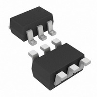
MCP4018T-103E/LT Microchip Technology, MCP4018T-103E/LT Datasheet - Page 15

MCP4018T-103E/LT
Manufacturer Part Number
MCP4018T-103E/LT
Description
IC DGTL POT 10K 128TAPS SC70-6
Manufacturer
Microchip Technology
Datasheet
1.MCP4018T-502ELT.pdf
(66 pages)
Specifications of MCP4018T-103E/LT
Package / Case
SC-70-6, SC-88, SOT-363
Temperature Coefficient
150 ppm/°C Typical
Taps
128
Resistance (ohms)
10K
Number Of Circuits
1
Memory Type
Volatile
Interface
I²C, 2-Wire Serial
Voltage - Supply
1.8 V ~ 5.5 V
Operating Temperature
-40°C ~ 125°C
Mounting Type
Surface Mount
Resistance In Ohms
10K
Number Of Pots
Single
Taps Per Pot
128
Resistance
10 KOhms
Wiper Memory
Volatile
Buffered Wiper
Buffered
Digital Interface
Serial (2-Wire, I2C)
Operating Supply Voltage
2.5 V or 3.3 V or 5 V
Supply Current
0.045 mA (Typ)
Maximum Operating Temperature
+ 125 C
Minimum Operating Temperature
- 40 C
Description/function
7 Bit Single I2C Digital Potentiometer
Mounting Style
SMD/SMT
Supply Voltage (max)
5.5 V
Supply Voltage (min)
1.8 V
Tolerance
20 %
Lead Free Status / RoHS Status
Lead free / RoHS Compliant
Lead Free Status / RoHS Status
Lead free / RoHS Compliant, Lead free / RoHS Compliant
Other names
MCP4018T-103E/LTTR
Available stocks
Company
Part Number
Manufacturer
Quantity
Price
Company:
Part Number:
MCP4018T-103E/LT
Manufacturer:
MICROCHIP
Quantity:
12 000
Part Number:
MCP4018T-103E/LT
Manufacturer:
MICROCHIP/微芯
Quantity:
20 000
Note: Unless otherwise indicated, T
FIGURE 2-9:
(FSE) vs. Temperature (V
FIGURE 2-10:
(ZSE) vs. Temperature (V
FIGURE 2-11:
(
© 2009 Microchip Technology Inc.
Ω
) vs. Temperature and V
-0.2
-0.4
-0.6
-0.8
-1.0
-1.2
-1.4
-1.6
-1.8
1.8
1.6
1.4
1.2
1.0
0.8
0.6
0.4
0.2
0.0
5200
5180
5160
5140
5120
5100
5080
5060
5040
5020
5000
0.0
-40
-40
-40
Ambient Temperature (°C)
Ambient Temperature (°C)
0
Ambient Temperature (°C)
0
0
5.0 k
5.0 k
5.0 k
1.8V
Ω
Ω
Ω
DD
DD
40
40
DD
40
: Nominal Resistance
: Full Scale Error
: Zero Scale Error
= 5.5V, 2.7V, 1.8V).
= 5.5V, 2.7V, 1.8V).
2.7V
.
2.7
1.8V
A
5.5V
5.5V
1.8V
= +25°C, V
80
80
80
5.5V
2.7
120
120
120
DD
= 5V, V
SS
= 0V.
FIGURE 2-12:
Δ
FIGURE 2-13:
Response Time.
FIGURE 2-14:
(SCL signal coupling to Wiper pin).
R
WB
Wiper
/
200
180
160
140
120
100
V
80
60
40
20
Δ
DD
0
T vs. Code.
0
MCP4017/18/19
Wiper Setting (decimal)
32
5.0 k
5.0 k
5.0 k
2.7V
64
Ω
Ω
Ω
: R
: Power-Up Wiper
: Digital Feedthrough
BW
5.5V
96
DS22147A-page 15
Tempco


