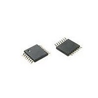
MAX5389LAUD+ Maxim Integrated Products, MAX5389LAUD+ Datasheet - Page 9

MAX5389LAUD+
Manufacturer Part Number
MAX5389LAUD+
Description
IC POT DGTL 256-TAP 14TSSOP
Manufacturer
Maxim Integrated Products
Datasheet
1.MAX5389MAUD.pdf
(13 pages)
Specifications of MAX5389LAUD+
Taps
256
Resistance (ohms)
10K
Number Of Circuits
2
Temperature Coefficient
35 ppm/°C Typical
Memory Type
Volatile
Interface
Up/Down
Voltage - Supply
2.6 V ~ 5.5 V
Operating Temperature
-40°C ~ 125°C
Mounting Type
Surface Mount
Package / Case
14-TSSOP
Resistance In Ohms
10K
Number Of Pots
Dual
Taps Per Pot
256
Resistance
200 Ohms
Wiper Memory
Volatile
Digital Interface
Up/Down
Operating Supply Voltage
2.6 V to 5.5 V
Supply Current
1 uA
Maximum Operating Temperature
+ 125 C
Minimum Operating Temperature
- 40 C
Description/function
Dual Up/Down Interface Digital Potentiometer
Mounting Style
SMD/SMT
Supply Voltage (max)
5.5 V
Supply Voltage (min)
2.6 V
Tolerance
25 %
Lead Free Status / RoHS Status
Lead free / RoHS Compliant
The MAX5389 dual, 256-tap, volatile, low-voltage linear
taper digital potentiometer offers three end-to-end resis-
tance values of 10kI, 50kI, and 100kI. The potenti-
ometer consists of 255 fixed resistors in series between
terminals H_ and L_. The potentiometer wiper, W_, is
programmable to access any one of the 256 tap points
on the resistor string. On power-up, the wiper position is
set to midscale (tap 128).
The potentiometers are programmable independent of
each other. The MAX5389 features an up/down interface.
Logic inputs CS_, UD_, and INC_ determine the wiper
position of the device (Table 1). With CS_ low and UD_
high, a high-to-low (falling edge) transition on INC_
increments the internal counter which moves the wiper,
W_, closer to H_. When both CS_ and UD_ are low, the
falling edge of INC_ decrements the internal counter
Figure 2. Up/Down Interface Timing Diagram
INC_
UD_
CS_
W_
_______________________________________________________________________________________
Detailed Description
t
DI
t
CI
Dual, 256-Tap, Volatile, Low-Voltage
Linear Taper Digital Potentiometer
Up/Down Interface
t
ID
t
IW
t
IL
and moves the tap point, W_ closer to L_, (Figure 2). The
wiper performs a make-before-break transition ensuring
that W_ is never disconnected from the resistor string
during a transition from one tap point to another. When
the wiper is at either end of the resistor array additional
transitions in the direction of the end point do not change
the counter value.
Table 1. Up/Down Control Table
X = Don’t care.
↑ = Low-to-high transition.
↓ = High-to-low transition.
t
IH
CS_
H
L
L
L
L
t
IC
UD_
H
H
X
L
L
INC_
á
á
â
â
X
No change
No change
No change
Decrement
Increment
W_
9


