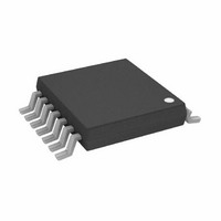
AD7376ARUZ10-R7 Analog Devices Inc, AD7376ARUZ10-R7 Datasheet - Page 8

AD7376ARUZ10-R7
Manufacturer Part Number
AD7376ARUZ10-R7
Description
IC DIGITAL POT 10K 14-TSSOP
Manufacturer
Analog Devices Inc
Datasheet
1.AD7376ARWZ100.pdf
(20 pages)
Specifications of AD7376ARUZ10-R7
Taps
128
Resistance (ohms)
10K
Number Of Circuits
1
Temperature Coefficient
300 ppm/°C Typical
Memory Type
Volatile
Interface
SPI, 3-Wire Serial
Voltage - Supply
4.5 V ~ 33 V, ±4.5 V ~ 16.5 V
Operating Temperature
-40°C ~ 85°C
Mounting Type
Surface Mount
Package / Case
14-TSSOP
Resistance In Ohms
10K
End To End Resistance
10kohm
Track Taper
Linear
No. Of Steps
128
Resistance Tolerance
± 30%
Supply Voltage Range
4.5V To 33V, ± 4.5V To ± 16.5V
Control Interface
Serial, SPI
Number Of Elements
1
# Of Taps
128
Resistance (max)
10KOhm
Power Supply Requirement
Single/Dual
Interface Type
Serial (3-Wire/SPI)
Single Supply Voltage (typ)
15V
Dual Supply Voltage (typ)
±15V
Single Supply Voltage (min)
4.5V
Single Supply Voltage (max)
33V
Dual Supply Voltage (min)
±4.5V
Dual Supply Voltage (max)
±16.5V
Operating Temp Range
-40C to 85C
Operating Temperature Classification
Industrial
Mounting
Surface Mount
Pin Count
14
Lead Free Status / RoHS Status
Lead free / RoHS Compliant
For Use With
EVAL-AD7376EBZ - BOARD EVAL FOR AD7376
Lead Free Status / Rohs Status
Compliant
Other names
AD7376ARUZ10-R7TR
AD7376
PIN CONFIGURATIONS AND FUNCTION DESCRIPTIONS
Table 6.Pin Function Descriptions
14-Lead
TSSOP
1
2
3
4
5
6
7
8
9
10
11
12
13
14
1
Assert shutdown and program the device during power-up. Then, deassert the shutdown to achieve the desirable preset level.
Pin No.
Figure 4. 14-Lead TSSOP Pin Configuration
16-Lead
SOL
1
2
3
4
5
6
7
8, 9, 10
11
12
13
14
15
16
GND
CLK
V
CS
RS
SS
A
B
1
2
3
4
5
6
7
NC = NO CONNECT
(Not to Scale)
AD7376
TOP VIEW
A
B
GND
CLK
SDI
SDO
NC
W
Mnemonic
V
CS
RS
NC
SHDN
V
SS
DD
14
13
12
10
11
9
8
W
NC
V
SDO
SHDN
SDI
NC
DD
A Terminal. V
B Terminal. V
Digital Ground.
Serial Data Input (data loads MSB first).
No Connect. Let it float or ground.
Wiper Terminal. V
Description
Negative Power Supply.
Chip Select Input, Active Low. When CS returns high, data is loaded into the wiper register.
Reset to Midscale.
Serial Clock Input. Positive edge triggered.
No Connect. Let it float or ground.
Shutdown. A terminal open ended; W and B terminals shorted. Can be used as
programmable preset.
Serial Data Output.
Positive Power Supply.
SS
SS
Rev. C | Page 8 of 20
≤ V
≤ V
SS
B
A
≤ V
≤ V
≤ V
DD
1
W
DD
≤ V
.
.
DD
.
Figure 5. 16-Lead SOIC_W Pin Configuration
GND
CLK
V
NC
CS
RS
SS
A
B
1
2
3
4
5
6
7
8
NC = NO CONNECT
(Not to Scale)
AD7376
TOP VIEW
16
15
14
13
12
11
10
9
W
NC
V
SDO
SHDN
SDI
NC
NC
DD


